Bare-metal programming: Write your first Assembly program
Have you ever wondered what actually happens inside your computer when you type a command or execute a program?
When you write code in high-level languages like Python, C, or JavaScript, everything feels clean and friendly. But down at the hardware level, physical silicon chips do not understand high-level concepts like functions, classes, or conditional branches. They only process pulses of electricity that represent zeroes and ones.
You might remember that we use compilers to turn high-level languages into binary executables. A compiler is simply another program. Its job is to translate human-readable source code into something closer to the metal: Assembly language, and ultimately, machine code instructions.
In this tutorial, we will take a practical journey down to the metal. We will examine how computers execute code, explore CPU architectures, clock cycles, and kernels, see how Assembly evolved from human-punched cards, and write an x86_64 Assembly program.
Step 1: What is a Computer, CPU Architecture, & The Clock Cycle?
If you opened a computer case and looked closely at the processor, you would see a small square of silicon containing billions of microscopic transistors. But how does that physical chip run software?
Fundamentally, a computer is an electronic machine that carries out three steps continuously:
- Fetch: Read the next instruction from main memory (RAM).
- Decode: Interpret what that instruction is asking the CPU to do.
- Execute: Perform the operation and store the result.
The Heartbeat of the CPU: The Clock Cycle
This continuous cycle is driven by an internal quartz oscillator called the CPU Clock.
When a processor is rated at 3.5 GHz, its CPU clock ticks 3.5 billion times every second. Each tick represents one Clock Cycle. Simple assembly instructions (such as moving a value into a register) may execute in a single clock cycle, while more complex operations can require multiple cycles.
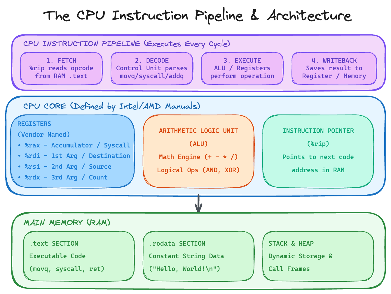
The CPU Instruction Pipeline & Architecture: Fetch, Decode, Execute, and Writeback stages driving CPU Registers, the ALU, and Memory.
To execute instructions, the CPU relies on three core internal components:
- Registers: Small, ultra-fast storage locations built directly inside the CPU core (such as
%rax,%rdi, or%rspon 64-bit Intel and AMD processors). They serve as the CPU's immediate workspace. - Arithmetic Logic Unit (ALU): The mathematical engine that performs arithmetic operations (addition, subtraction) and logical operations (AND, XOR).
- Instruction Pointer (
%rip): A specialized register holding the memory address of the next instruction waiting to be fetched.
Who Names the Registers? (The Vendor Manuals)
Why are x86_64 registers named %rax, %rdi, or %rsi, while ARM64 uses x0, x1, x2?
Whoever designs and manufactures the physical CPU chip (such as Intel, AMD, or ARM) defines its Instruction Set Architecture (ISA). The chip vendor names every register, specifies every binary opcode, and documents how each instruction behaves.
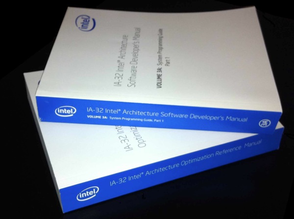
The Intel 64 and IA-32 Architectures Software Developer's Manual: the authoritative reference for x86_64 hardware behavior.
These details are published in comprehensive vendor documentation, such as the multi-volume Intel 64 and IA-32 Architectures Software Developer's Manual and the AMD64 Architecture Programmer's Manual. Compiler authors and assembly programmers rely on these manuals as the authoritative reference on hardware behavior.
Step 2: System Calls: The Bridge to the Kernel
If any application running on a computer could directly modify storage hardware or overwrite memory belonging to other applications, a single buggy process could easily corrupt memory or crash the entire system.
To maintain stability and safety, CPUs enforce hardware execution constraints:
- User Mode (Userspace): A constrained mode where regular applications run. The CPU prevents your code from accessing memory outside its assigned address space or touching physical hardware directly.
- Kernel Mode: An unconstrained mode reserved for the Operating System Kernel, which manages physical hardware, device drivers, and system memory safely.
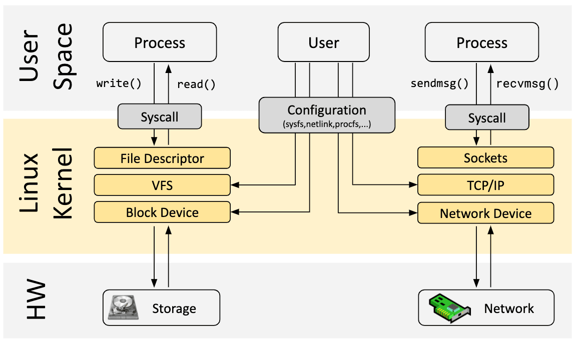
Linux Kernel Architecture overview showing how applications interact with kernel subsystems via system calls (Source: ebpf.io).
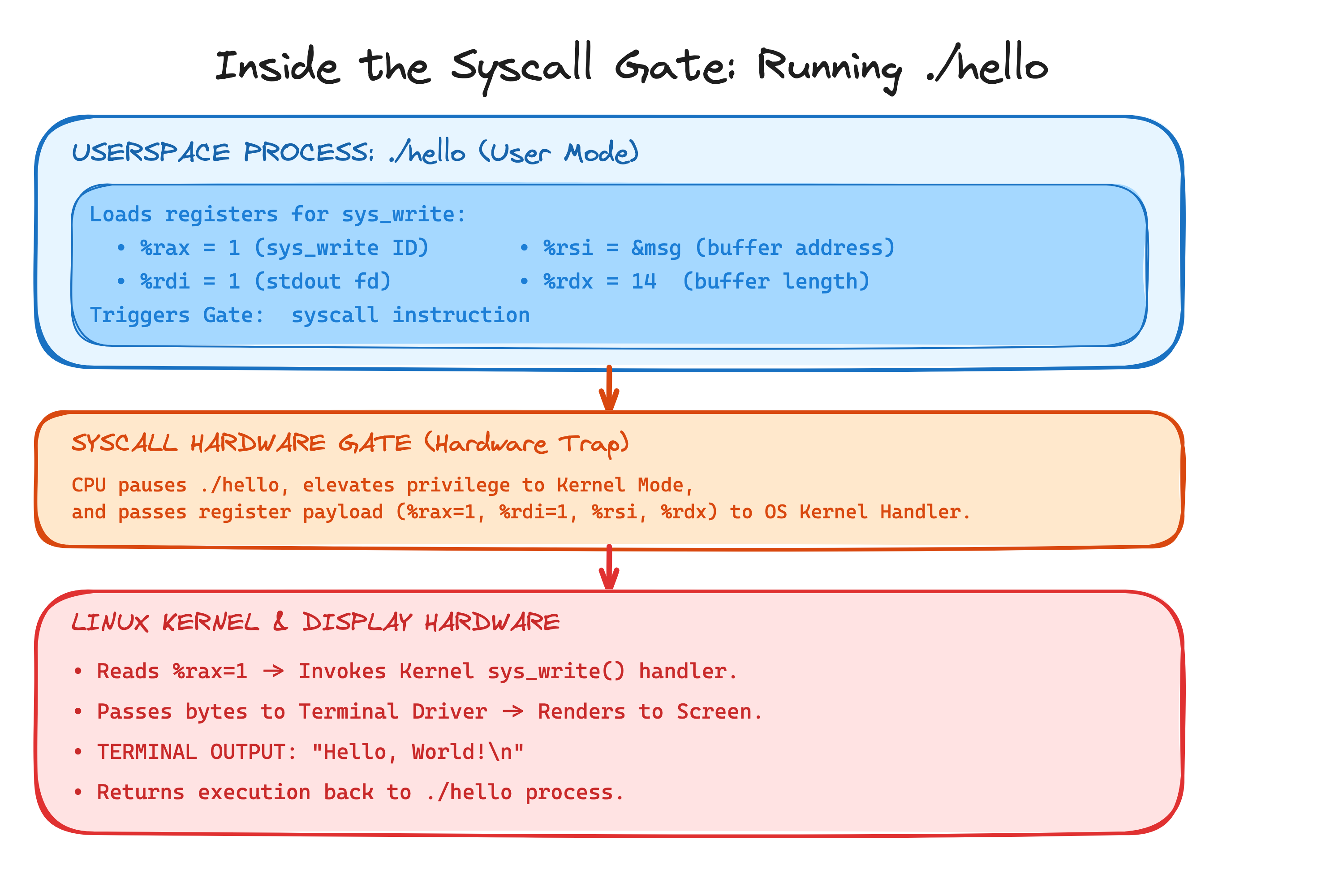
Inside the Syscall Gate: Step-by-step execution flow of the ./hello process passing registers across the hardware trap to the Kernel.
When an application needs to perform an I/O operation (such as printing text to the screen, reading a file, or exiting), it cannot touch the hardware directly. Instead, it requests assistance from the kernel using a System Call (Syscall).
The system call interface acts as a universal adapter between your application and physical hardware.
For example, imagine if every program had to write custom driver code specifically for an LG monitor, a Samsung display, or a Dell screen. If a user plugged in a different monitor, the app would crash. Instead, your program simply asks the kernel to perform a sys_write to stdout. The kernel translates that request into the exact electrical commands needed for whatever display or storage hardware is attached.
This stability is a fundamental guarantee provided by the kernel: as long as the operating system exposes the same system call interface, your application logic remains portable across different hardware devices and physical machines.
A system call follows these steps:
- Setup: The program loads argument values into specific CPU registers (
%raxfor the system call ID, and%rdi,%rsi,%rdxfor arguments). - The Trap Gate: The program executes the
syscallinstruction. - Privilege Switch: The CPU pauses the program, switches from Constrained User Mode to Unconstrained Kernel Mode, and jumps to the kernel's system call handler table.
- Hardware Execution: The kernel verifies permissions, interacts with hardware drivers (such as sending character bytes to the display), and returns execution control back to the userspace program.
Step 3: What is Assembly? (ISAs, CISC vs RISC, & History)
Assembly is not a single programming language. Because every CPU architecture has its own ISA defined by its vendor, assembly is a family of languages. An assembly program written for an x86_64 Intel processor looks quite different from one written for an ARM64 processor on Apple Silicon or mobile devices.
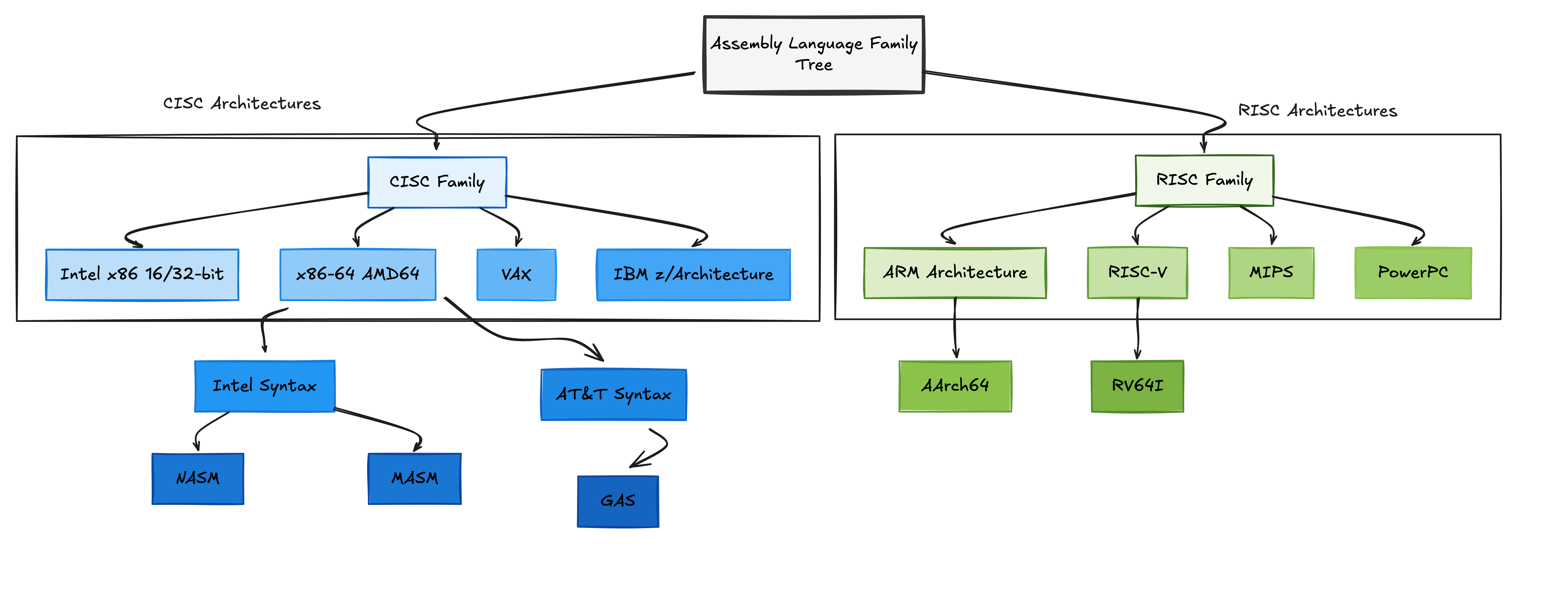
Assembly Language Family Tree: Key ISA branches comparing CISC (x86_64) and RISC (ARM64, RISC-V) architectures.
CISC vs. RISC: Two Philosophies
CPU architectures generally fall into two main design paradigms:
- CISC (Complex Instruction Set Computer) (e.g., x86_64):
CISC architectures provide feature-rich instructions. A single CISC instruction can read from memory, perform an arithmetic operation, and store the result back to memory in a single instruction.
# x86_64 (CISC): Add a value from memory directly into a register addq (%rbx), %rax - RISC (Reduced Instruction Set Computer) (e.g., ARM64, RISC-V):
RISC architectures use simple, uniform instructions. To perform arithmetic on data stored in memory, a RISC processor requires loading the data into a register first (a Load/Store model):
// ARM64 (RISC): Load from memory first, then perform addition
ldr x1, [x0]       // Load value from memory address in x0 into x1
add x2, x2, x1     // Add x1 to x2
The Early Days
If we use compilers to translate high-level code into assembly, and assemblers to turn assembly into binary machine code, how was the very first assembler created? What compiled the first compiler?
This classic chicken-and-egg question takes us back to the dawn of computing. Before modern keyboards, displays, or software tools existed, there were no automated programs to do the translation.
In the 1940s and 1950s, the first "assemblers" were human programmers. Developers wrote their code on paper, looked up instruction tables manually, and translated assembly mnemonics into raw binary opcodes. They then encoded these opcodes by punching holes into paper punch cards.
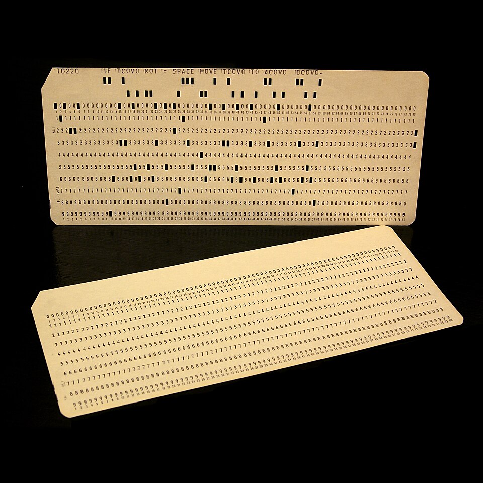
Historical 80-column IBM punch cards used for encoding early computer programs (Source: Wikipedia).
Developers would submit stacks of punch cards at computing centers, hand them to operators, and wait in batch queues to verify whether their program succeeded or failed. Once humans wrote an initial assembler directly in raw binary opcodes, that basic assembler could finally be used to assemble more advanced tools. This process is known as bootstrapping.
The Cost of a Typo & The Origin of "Patching"
In the punch card era, a single typo or misplaced hole carried a heavy cost. A developer had to wait hours or even overnight in batch queues just to receive a printout indicating a syntax error.
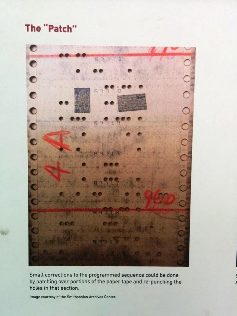
A physical punch card with adhesive tape patches covering incorrect holes, demonstrating the origin of the software term "patching".
To avoid re-punching an entire stack of cards, programmers physically glued small pieces of paper or adhesive tape over misplaced holes to restore the paper surface, or re-punched corrected holes over the covered areas. This physical repair of damaged code is where the modern software engineering term "patching" (and "software patch") originated.
Step 4: Write your first x86_64 Assembly program
Now let's write, assemble, and run an x86_64 assembly program from scratch in your Linux environment.
1. Create your exercise workspace
Create a dedicated directory for your assembly experiments:
mkdir -p ~/exercise && cd ~/exercise
2. Write the source code (hello.s)
Create a file named hello.s with the following content:
.text
.globl _start

_start:
    movq $1, %rax           # Syscall #1: sys_write
    movq $1, %rdi           # Argument 1: stdout (file descriptor 1)
    leaq msg(%rip), %rsi    # Argument 2: pointer to string buffer
    movq $14, %rdx          # Argument 3: length of string (14 bytes)
    syscall                 # Request the kernel to write text to stdout

    movq $60, %rax          # Syscall #60: sys_exit
    xorq %rdi, %rdi         # Argument 1: exit status 0 (success)
    syscall                 # Request the kernel to terminate the program

.section .rodata
msg:
    .ascii "Hello, World!\n"
Understanding the code step-by-step
Here is a breakdown of what happens when this file is processed:
.textand_start:.texttells the assembler that executable instructions follow._startspecifies the entry point symbol for the linker.- Preparing
sys_write:- We store
1in%raxto select system call #1 (sys_write). - We store
1in%rdito specify file descriptor 1 (stdout). - We load the string address into
%rsiand its byte length (14) into%rdx. - We execute
syscallto trigger the hardware gate.
- We store
- Preparing
sys_exit:- We store
60in%rax(sys_exit) and0in%rdi(success status). - We execute
syscallagain to exit cleanly.
- We store
If you are curious about system call numbers and register arguments for other operations on Linux (such as opening files or managing memory), you can inspect the Chromium OS Linux System Call Table.
3. Assemble, link, and run
Assemble hello.s into an object file using the GNU Assembler (as):
as hello.s -o hello.o
Link the object file into an executable binary using the GNU Linker (ld):
ld hello.o -o hello
Execute your assembly binary and verify its exit code:
./hello
echo $?
You should see Hello, World! printed to stdout, with 0 returned as the exit status.
Congratulations! You have now written, assembled, and executed an x86_64 assembly program directly on Linux. You have peeled back the layers of high-level abstractions, stepped across the system call boundary, and communicated directly with the kernel and hardware.
About the Author

Writes about
Frequently covers
More tutorials you might like
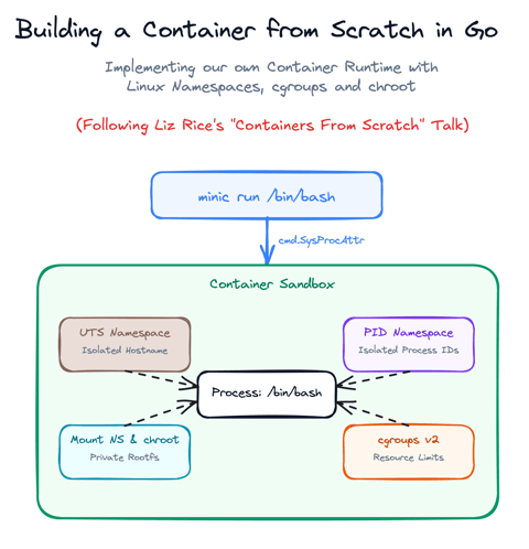
Build a Container from Scratch in Go (Liz Rice GOTO 2018)
Follow along with Liz Rice's classic GOTO 2018 presentation and build your own container runtime in under 100 lines of Go using Linux namespaces, chroot, and cgroups.

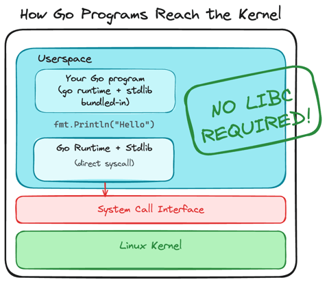
Using Go for Systems Programming
Discover how Go functions under the hood as a modern systems programming language. Learn how Go makes system calls directly, resulting in self-contained binaries that have no libc dependencies.
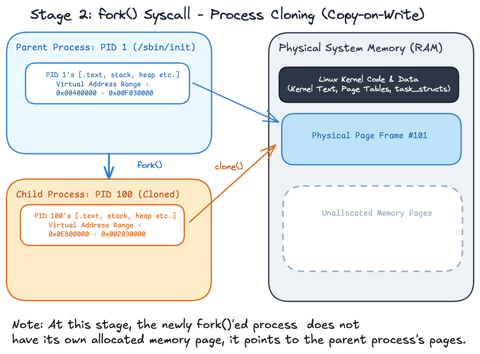
Linux Processes: From a Program to a Process
Explore what a program is, when it actually becomes a process and how the Linux scheduler manages process execution.
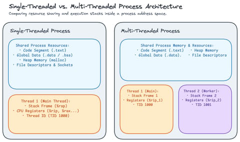
Linux Processes: Threads & Concurrency
Explore what a thread actually is in Linux, how threads relate to processes, how the Linux kernel treats both as tasks (task_struct), and how kernel scheduling enables concurrency.
Learn by doing, not just by reading or watching
Sign up for a free account to start a VM playground right on this page, track your progress, and get notified about new learning materials.