From LAN to VXLAN: Networking Basics for Non-Network Engineers
What is a LAN?
Starting with the most basic concept...
LAN (Local Area Network) - [broadly] a computer network that interconnects computers within a limited area such as a residence, school, office building, or data center. A LAN is not limited to a single IP subnetwork. Like a Wide area network (WAN), a LAN can consist of multiple IP networks communicating via routers. The main determinant of a LAN is the locality (i.e. proximity) of the participants, not the L3 topology.
What is a Network Link?
Network link - a physical and logical network component used to interconnect [any kind of] nodes in the network. All nodes of a single network link use the same link-layer protocol.
Examples:
- A group of computers connected to a network switch (Ethernet)
- A set of smartphones connected to a Wi-Fi access point (non-Ethernet)
- Etc.
What is a Network Segment?
Network segment - [again, broadly] a portion of a computer network. The actual definition of a segment is technology-specific. In the next units, we will cover different types of network segments.
What is an L1 Segment?
L1 segment (aka physical segment, aka Ethernet segment) - a network segment formed by an electrical (or optical) connection between networked devices using a shared medium. Nodes on a single L1 segment have a common physical layer.
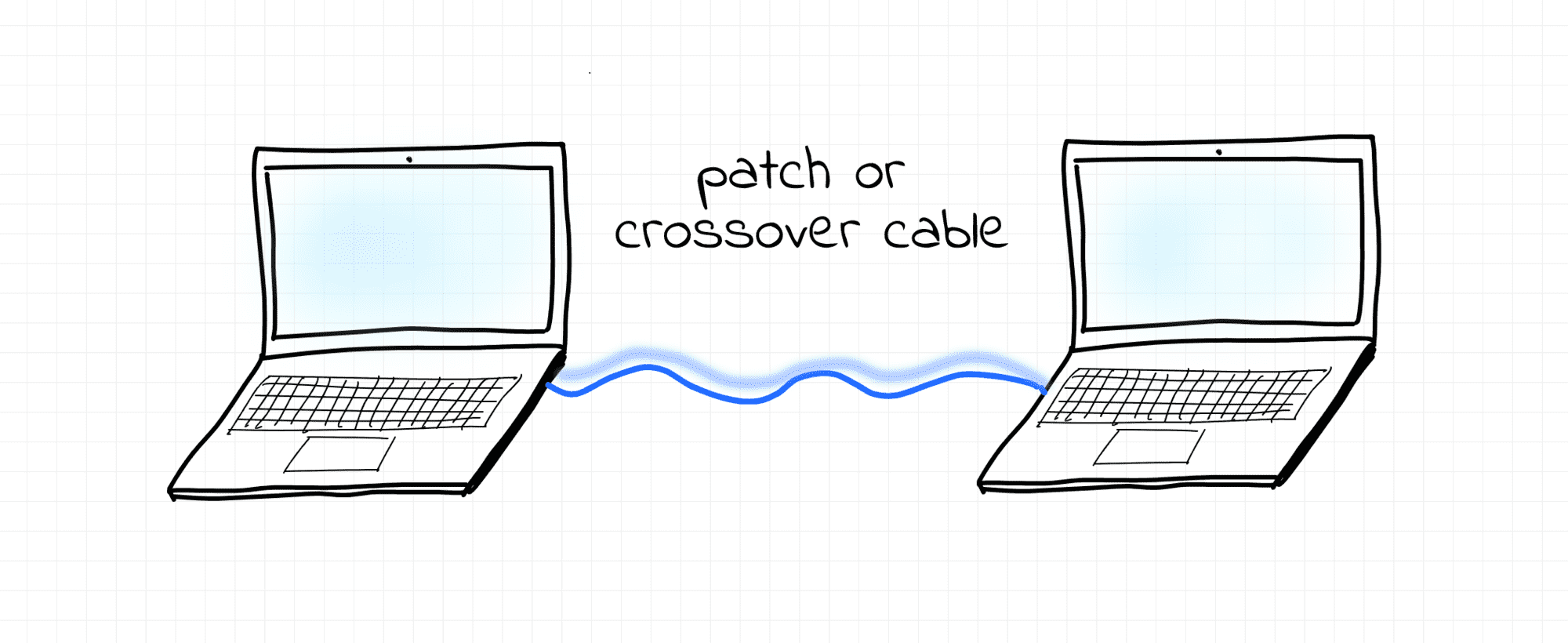
The simplest example of the contemporary L1 segment is a point-to-point connection between two end-nodes via a patch or crossover cable.
The most typical occurrence of L1 segment today, though, are the links between servers and the corresponding top-of-rack switch in a data center:
Blue lines are the L1 segments.
It's OK if the comic replicas on the picture above don't make much sense to you yet. The next unit will try to explain the evolution of the L1 segment technology that led to the modern switch devices.
Evolution of Physical Segments
In the early days of the Ethernet, a group of computers connected to a shared coaxial cable was forming a physical segment (aka bus topology). A coaxial cable served as a shared medium between multiple nodes. Everything sent by one of the nodes was seen by all other nodes of the segment. Thus, the nodes were forming a single broadcast domain.
This is OK because it had useful properties, which are still relied on today.
However, since multiple nodes could be transmitting frames simultaneously over a single cable, collisions were likely to occur. Hence, an L1 segment was also forming a single collision domain
This is undesirable and should be mitigated by hardware or software.
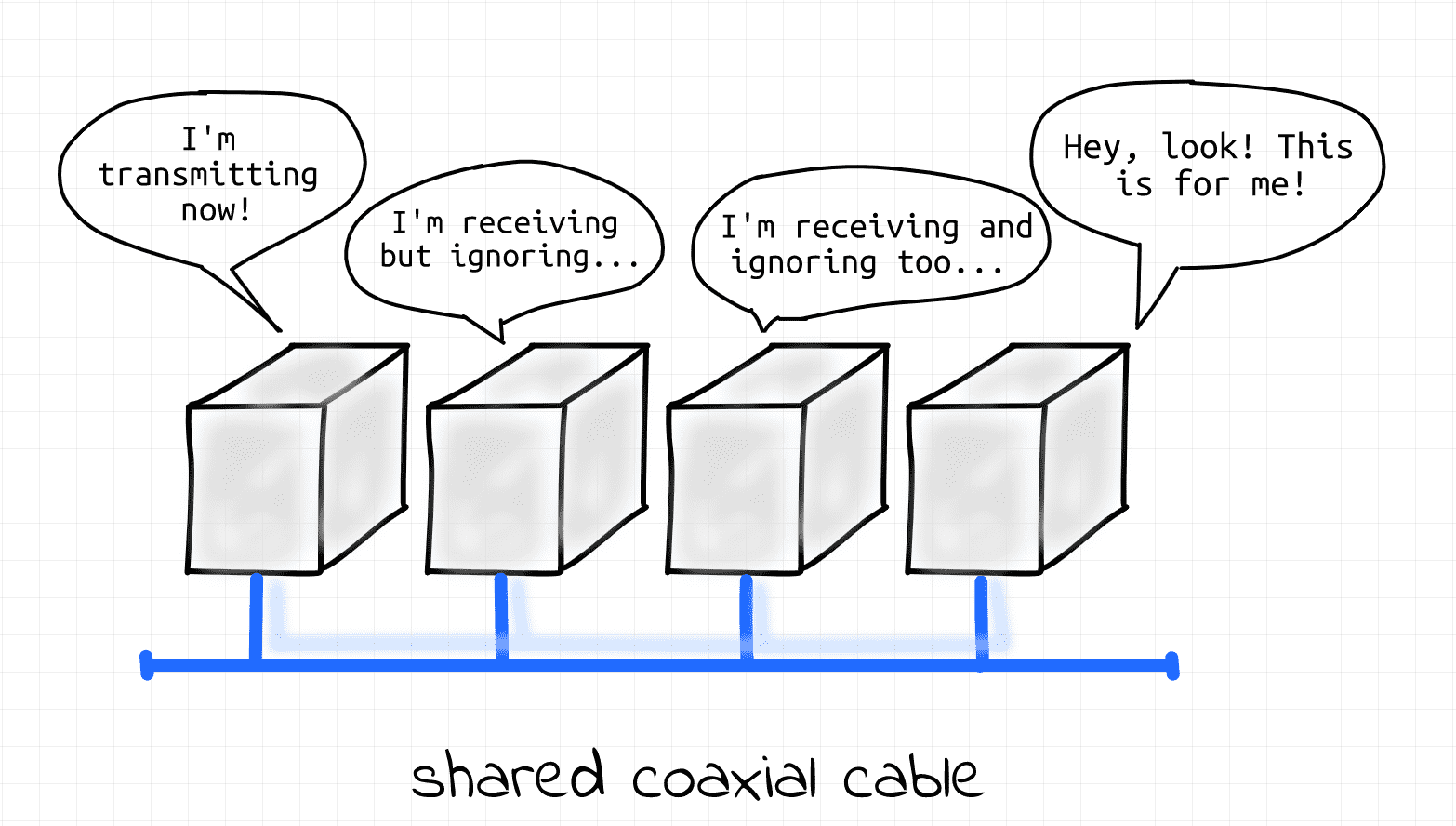
Ethernet as it started, 100 000 years ago.
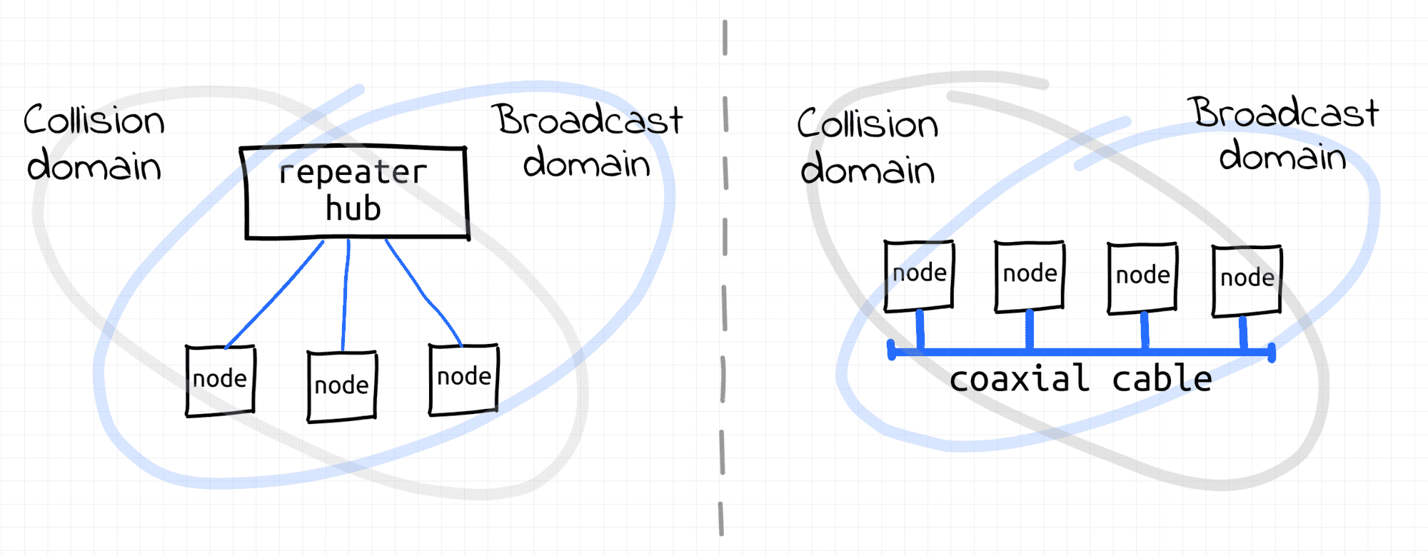
As an evolution of the Ethernet technology, twisted-pair cables connected to a common repeater hub replaced the shared coaxial cable (aka star topology). When a node on one of the hub's ports was transmitting frames, they were retransmitted from all the other ports of the hub. The retransmission of frames was as-is, i.e. no modification or filtration of frames was happening (hubs were pretty dumb devices). All nodes connected to the hub still were forming a single L1 segment (hence, a single broadcast domain 👌, hence a single collision domain 👎).
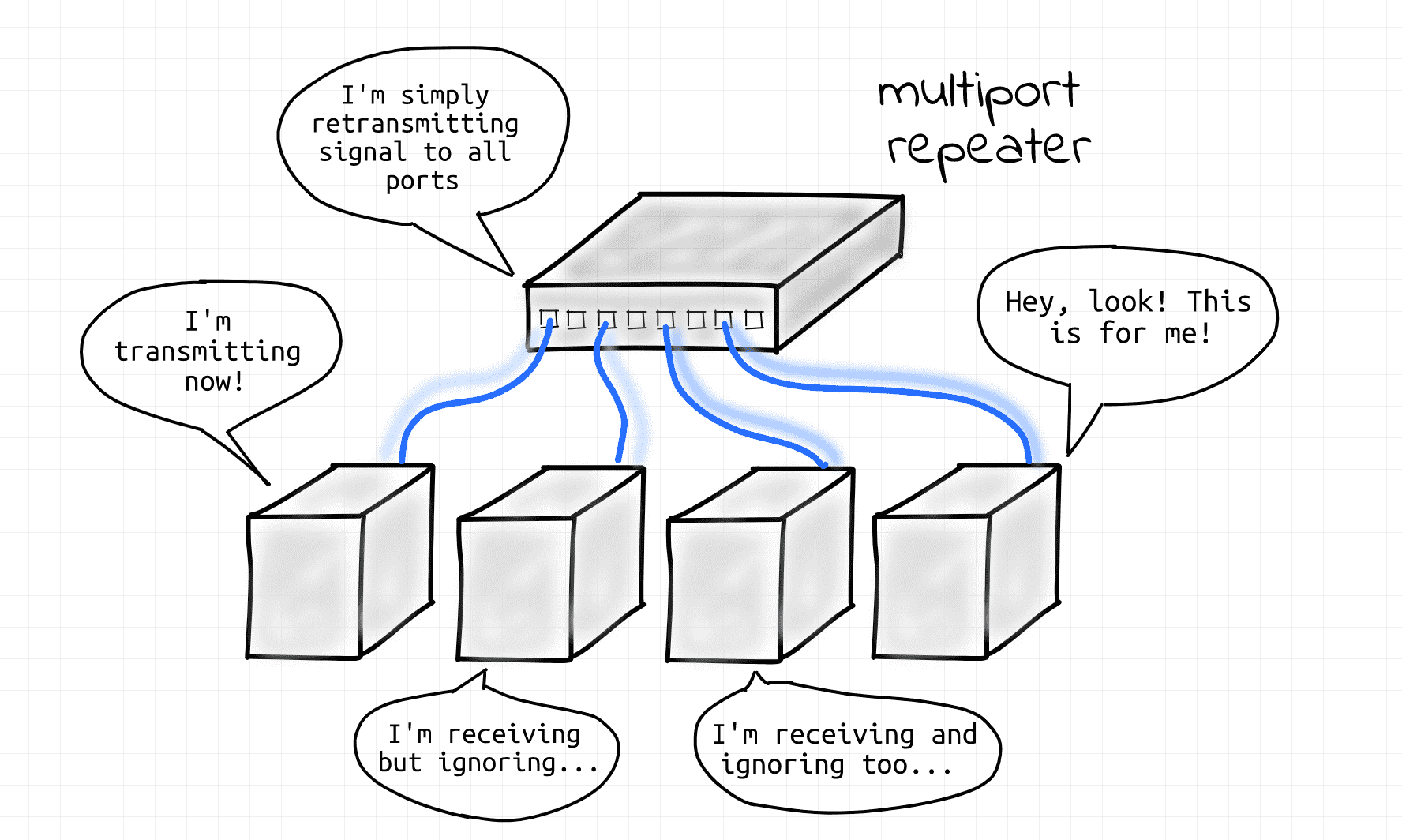
Evolution of Ethernet, 500 A.D.
Both coaxial and hub-based approaches are now obsolete!
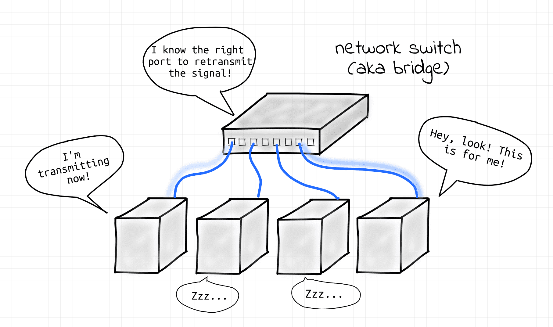
Today, the star topology is prevailing. However, hubs have been replaced by more advanced network switch devices (aka bridges). An L1 segment de facto was reduced to a single point-to-point link between an end-node and a switch (or a switch and another switch). Since there are only two nodes on a physical link the potential collision domain became very small.
Actually, most of the modern wiring is full-duplex, so collisions cannot occur at all.
Curious, what happened to the broadcast domain? Then keep reading!
Ethernet via network switch, present day.
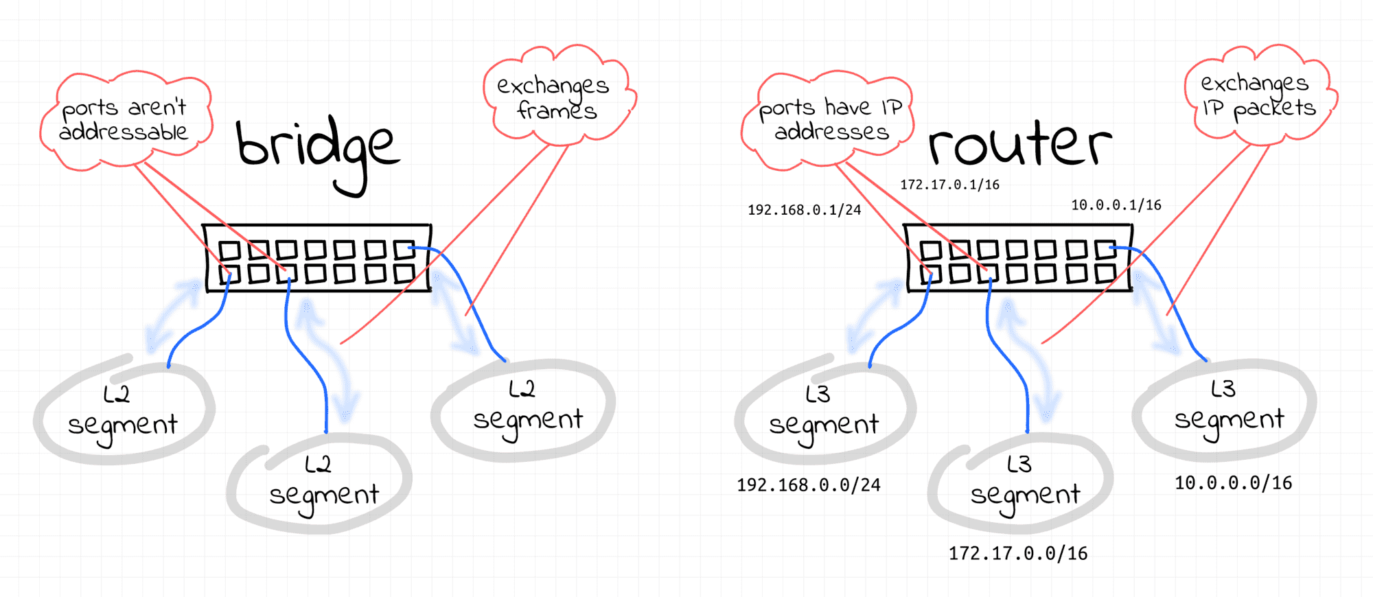
Beware that the terms switch and bridge that are used interchangeably in this lesson are in their original historical meaning.
Here, a bridge is a shortcut for a "multi-port bridge" and a switch is a shortcut for a "Layer 2 switch", which were pretty much the same thing back in the day. Today, these two devices, together with an L3 router, blended into one hardware device, often also called a "switch" (and its corresponding virtual device is called a "Linux bridge", so some confusion is inevitable). In the next lesson, we will discuss the difference between bridges and switches in more detail.
What is a Collision Domain?
Collision domain - a network segment (via a shared medium or hubs) where simultaneous data transmissions collide with one another.
The bigger a collision domain the worse for the network.
Nowadays, collision domains are common in wireless (i.e. non-Ethernet) networks, while back in the day they were common in Ethernet networks (see What is an L1 Segment).
In the old(er) Ethernet world, network switches (aka bridges) formed borders of collision domains
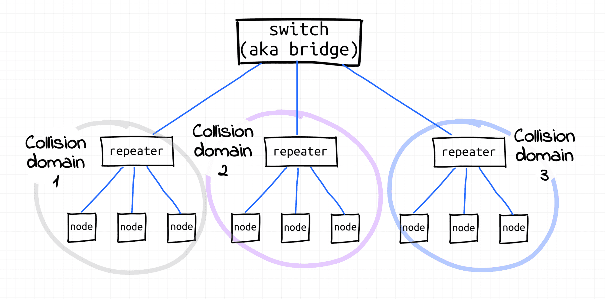
Three collision domains separated by a bridge (rather dated setup).
What is an L2 Segment?
L2 segment - multiple L1 segments interconnected using a shared switch (aka bridge) or (somewhat recursively) multiple L2 segments merged into a bigger L2 segment by an upper-layer switch where nodes can communicate with each other using their L2 addresses (MAC) or by broadcasting frames.
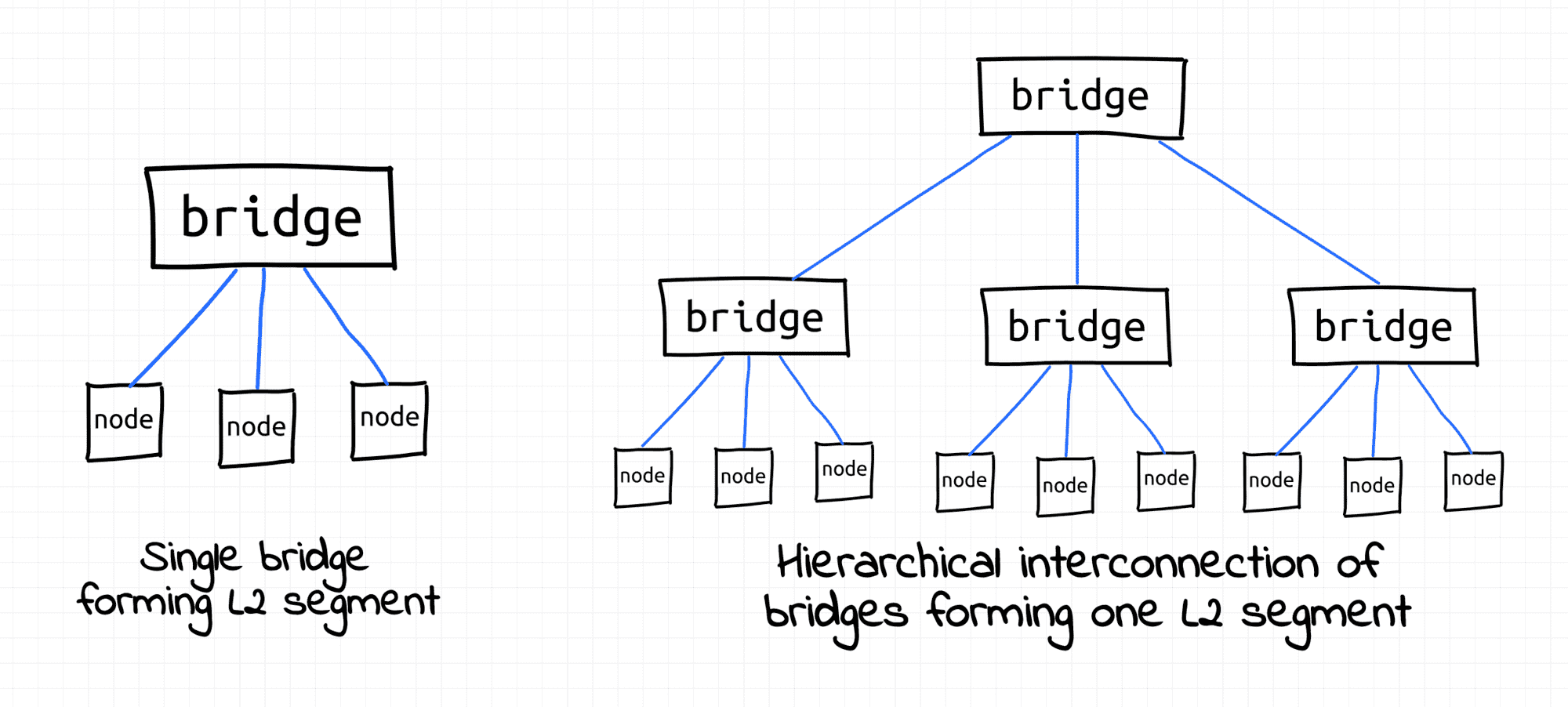
L2 segment examples.
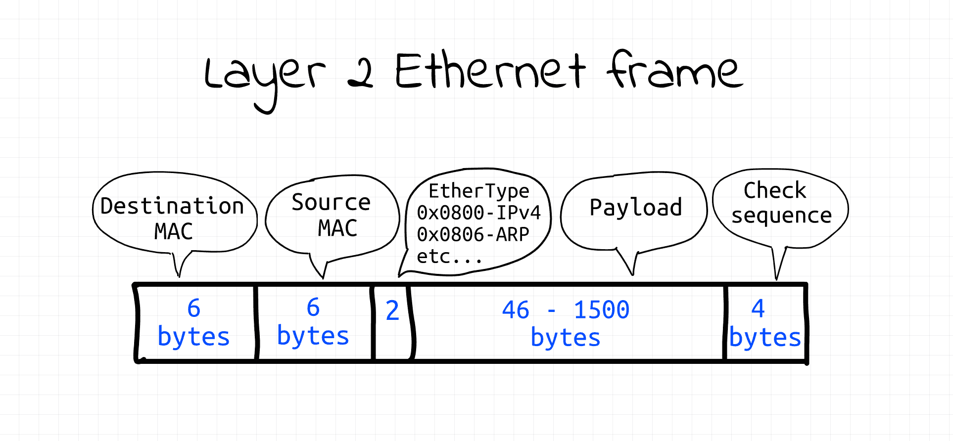
Layer 2 Ethernet frame - super simple format.
That's where things get interesting. If L1 segments are about the physical connectivity of nodes, L2 segments are rather about logical connectivity. The 1:1 and 1:all addressing provided by the Data link layer is vital for higher-layer protocols (ARP, IP, etc) implementations.
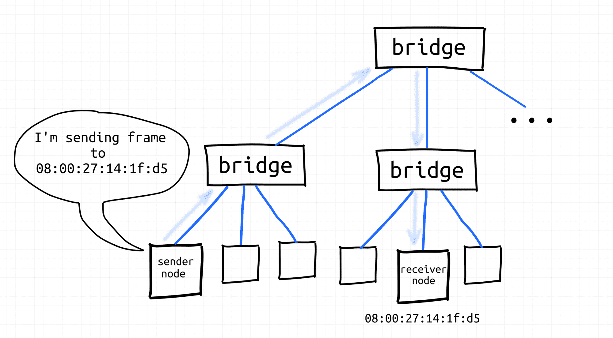
Node sends frame using destination MAC address.
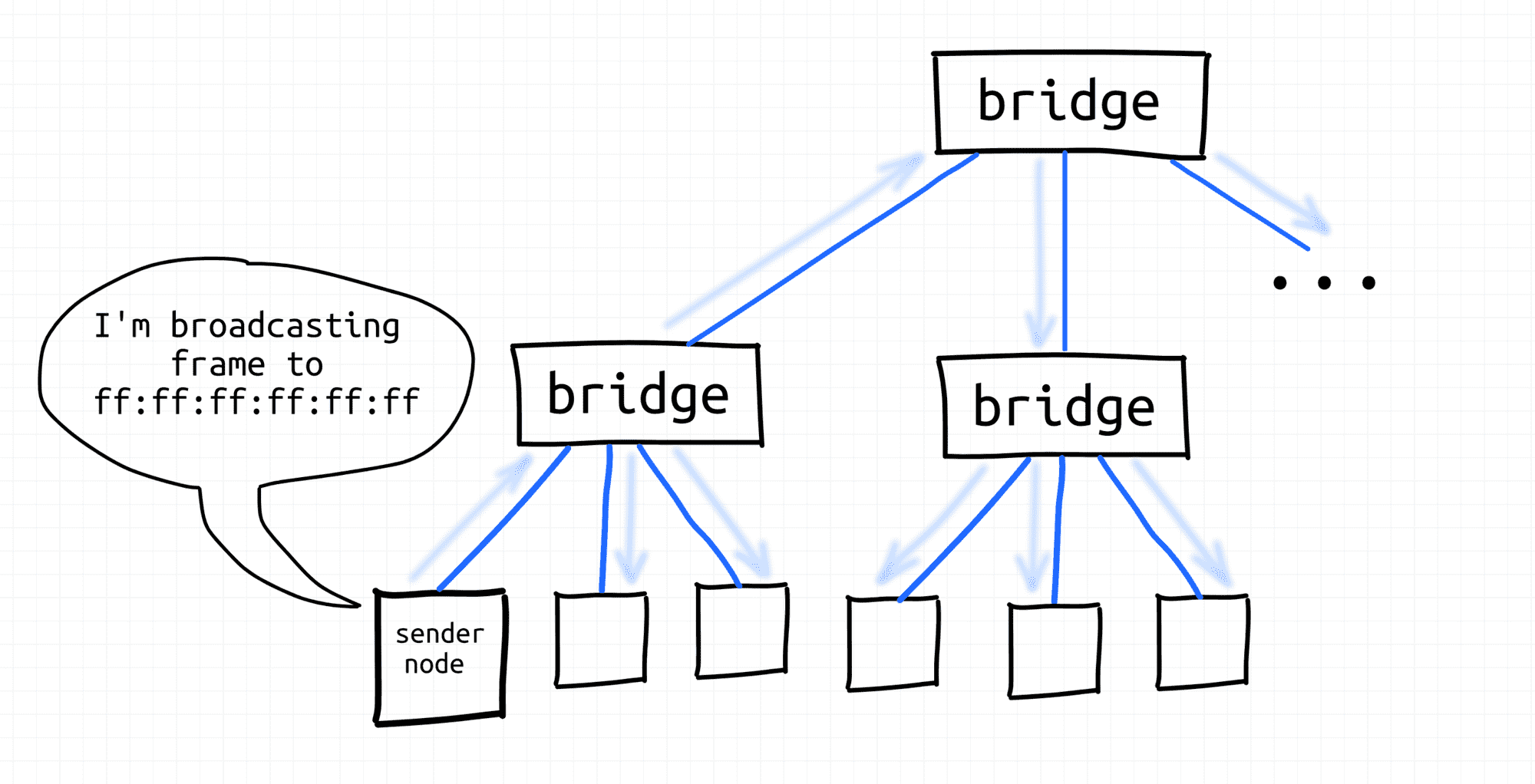
Node broadcasts frame.
We will spend more time practicing with the broadcasting mechanism in the future lessons of this course.
What is a Broadcast Domain?
Broadcast domain - all nodes of a single L2 segment, i.e. the nodes that can reach each other using a broadcast L2 address (ff:ff:ff:ff:ff:ff).
See the IP networks section to understand how L2 broadcast domains are used by higher layers.
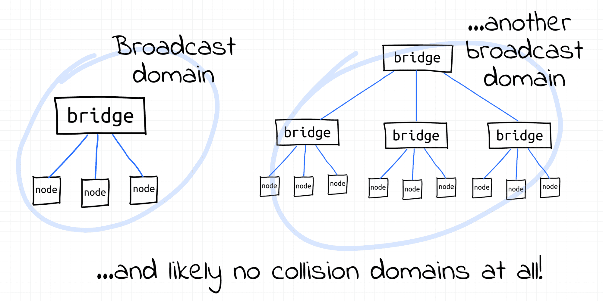
In the early days of the Ethernet, collision domains and broadcast domains were formed by physically interconnected nodes. I.e. a typical broadcast domain would consist of all nodes of an L1 segment and such a broadcast domain would be equal to the underlying collision domain. But if the collision domain was a misfortunate byproduct of the direct interconnection of nodes, the broadcast capabilities of such interconnection came in handy. So, the historical fight with collisions didn't affect the borders of broadcast domains.
With the invention of transparent bridges, it became possible to extend broadcast domains without extending collision domains by bridging multiple L1 segments using network switches. Nowadays, hierarchical topologies of interconnected switches are used to form multi-thousand hosts broadcast domains.
Normally, L3 routers form borders of broadcast domains. However, VLAN can be configured to split a single L2 segment into multiple non-intersecting L2 segments, hence - broadcast domains.
In one of the future lessons of this course, we will see how to use a Linux bridge (virtual network switch) to extend broadcast domains.
What is a VLAN?
VLAN - [broadly] any broadcast domain that is partitioned and isolated at the data link layer (L2).
VLANs are usually created by tagging Ethernet frames of a single L2 segment with some integer IDs (so-called VIDs), each ID forming a separate broadcast (sub-)domain.
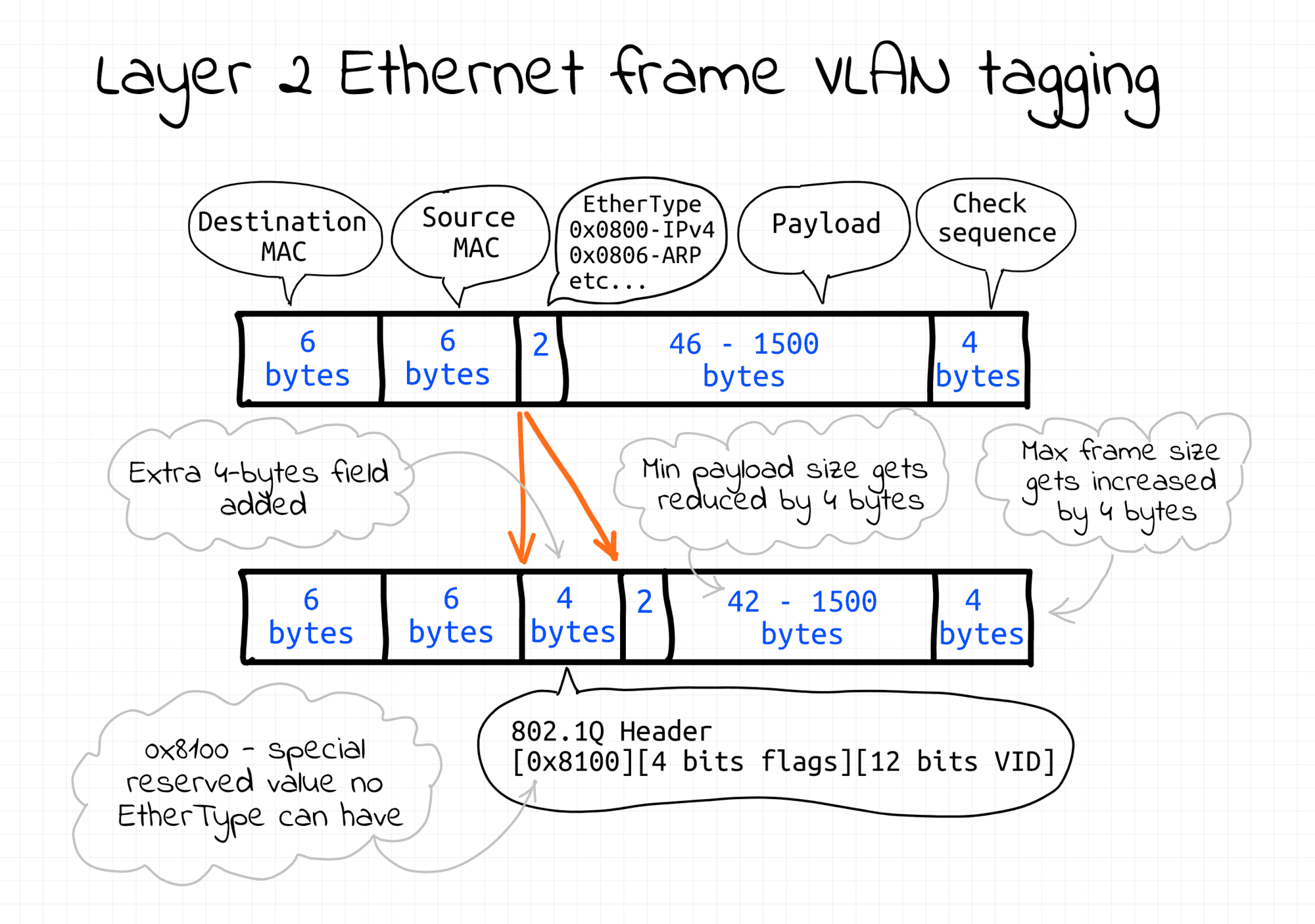
Frames with different IDs logically belong to different networks. This creates the appearance and functionality of network traffic that is physically on a single network segment but acts as if it is split between separate network segments. VLANs can keep network applications separate despite being connected to the same physical (or virtual) network.
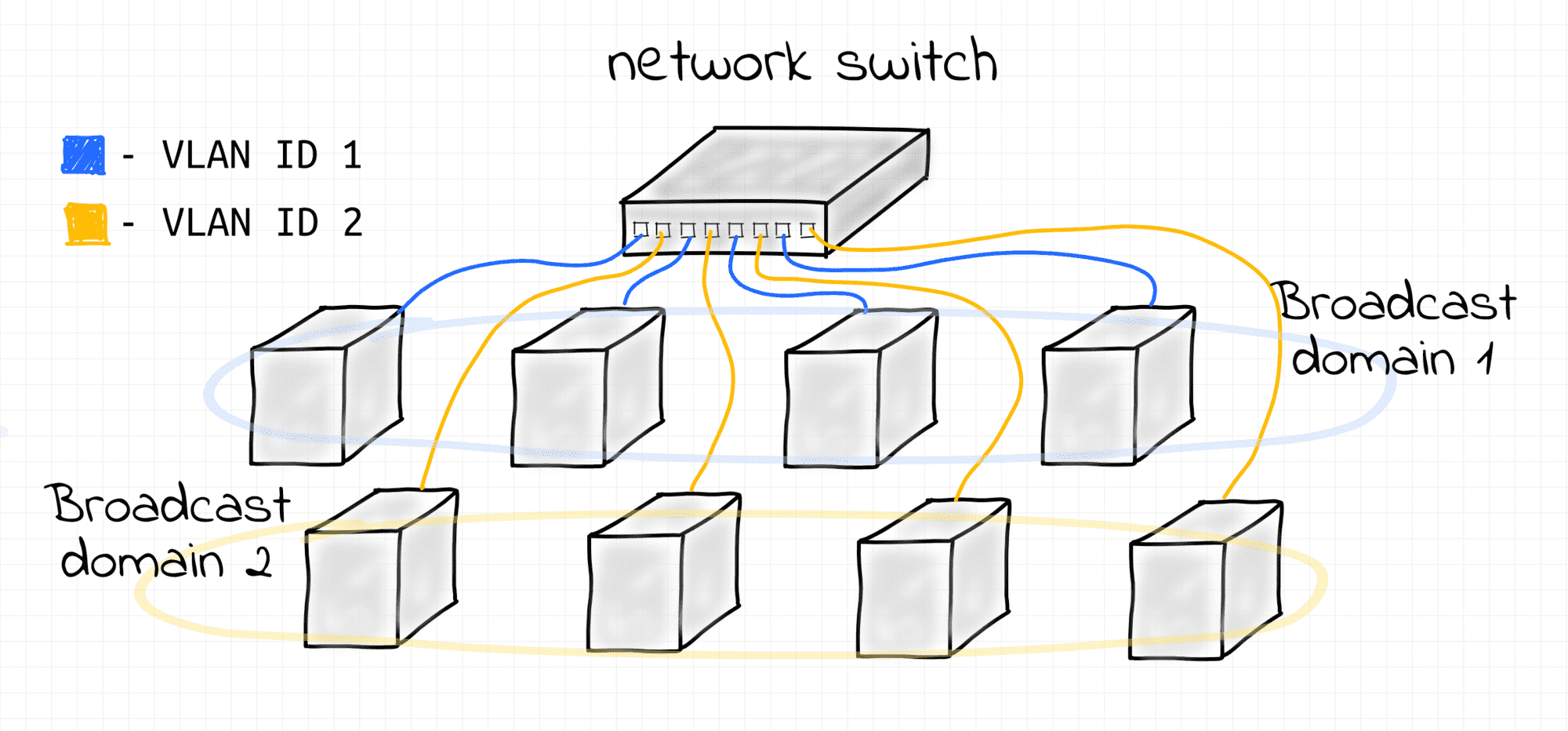
Two Virtual LANs on a single bridge.
The VLAN technology can be seen as inverse to bridging. Bridges merge multiple L2 segments (and broadcast domains) into one bigger L2 segment. VLANs split a single L2 segment (potentially formed by bridging multiple smaller L2 segments) into multiple non-intersecting L2 segments (and broadcast domains).
Check out this practical lesson for how to set up a simple VLAN using a Linux bridge.
What is an L3 Segment?
L3 segment - same as IP subnetwork (e.g. 192.168.0.0/24 or 172.18.0.0/16).
Notice, that up to this point we haven't been talking about IP (L3) addressing.
Communication within a single L2 segment required only MAC (L2) addresses.
We know, that when a node emits a frame with a certain destination MAC address,
it'll be delivered by the underlying L2 networking means to the destination node.
Additionally, any node can emit a broadcast frame with the destination MAC ff:ff:ff:ff:ff:ff and it'll be delivered to all the nodes of its L2 segment.
But how a node can reach another node (on the same L3 segment) by its IP address?
How IP Packets Are Sent within L3
First and foremost, IP packets are sent wrapped into Ethernet frames (assuming the Layer 2 protocol in use is Ethernet, of course). I.e. IP protocol data units (packets) are encapsulated in the Ethernet protocol data units (frames).
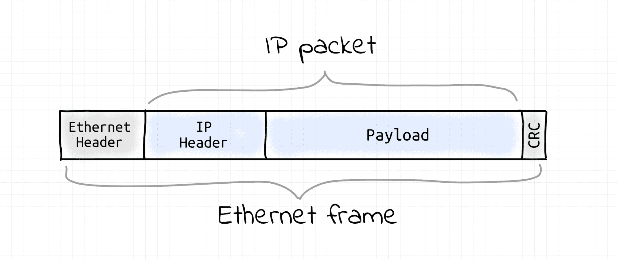
Thus, the task of sending an IP packet within an L3 segment boils down to sending an Ethernet frame with the IP packet inside to the L2 segment's node that owns that destination IP. Hence, the sending node needs to learn the receiving node's MAC address first. So, some sort of L3 (IP) to L2 (MAC) address translation mechanism is required. This is usually done by a Neighbor Discovery Protocol (ARP for IPv4 and NDP for IPv6) that relies on L2 broadcast capabilities.
When the IP to MAC translation is not known, the transmitting node sends a broadcast L2 frame with a query like "Who has IP 192.168.38.12?" expecting to get back a point-to-point L2 response from the owner of that IP. Such response will obviously contain the MAC address of the node possessing the requested IP. Once the destination MAC address is known for the sender node, it just wraps an IP packet into an L2 frame destined to that MAC address. Thus, an L3 segment heavily relies on the underlying L2 segment capabilities.
L3 to L2 Segment Relationship
There is an interesting relationship between L3 and L2 segment borders. It's pretty common to have a 1:1 mapping of L3 and L2 segments. However, technically nothing prevents us from having multiple L3 segments over a single L2 broadcast domain.
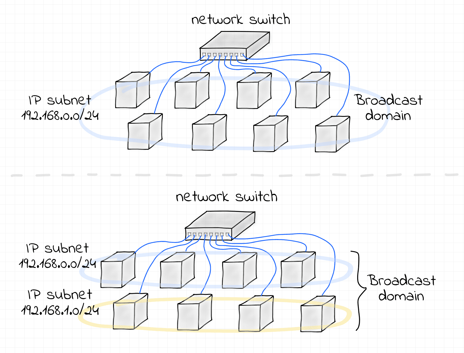
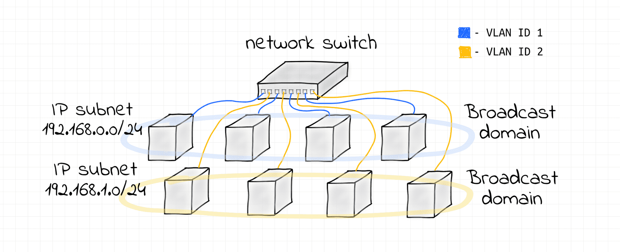
If stricter isolation is required, VLANs can be configured to split the L2 segment into multiple non-intersecting broadcast domains.
Interesting that in some (rather exceptional) cases, a single L3 segment can be configured over multiple L2 segments interconnected via a router. The technique is called Proxy ARP and it's documented in (rather dated) RFC 1027.
You will learn more about L3 to L2 segment mapping in the corresponding lesson of the course.
How IP Packets Are Sent Across L3
Communication between any two L3 segments always requires at least one router.
When a node wants to send an IP packet to a node that resides in another L3 segment (i.e., another IP subnet), it sends it to its gateway router instead. Since nodes can talk directly only with other nodes of the same L2 segment, one of the router's interfaces has to reside on the sender's L2 segment.
The IP address of the router is obtained from the routing table every node supposedly should have pre-configured.
Routers are usually connected to multiple network segments simultaneously, and when the gateway router gets such a frame, it unwraps it and resends the underlying IP packet using one of its other interfaces.
Thus, the cross-L3 packet sending procedure is pretty much the same as if the destination node was in the same L2 segment, but instead of directing an Ethernet frame with the wrapped IP packet in it to the final destination's MAC address (which can hardly be known to the sender now), the node passes it to the next-hop router and then the router does the same thing, and so on, until the packet reaches an L2 segment the destination node is connected to.
In interesting corollary to this - a next-hop router of every router has to reside on one of the L2 segments the router is directly connected to.
What is a VXLAN?
VXLAN - another network virtualization technology, somewhat similar to VLAN but much more powerful.
To some extent, VLAN can be considered as an overlay network. I.e. VLAN allows one to create multiple virtual segments on top of an existing network segment. However, there are some significant limitations. VLAN assumes that there is already a broadcast domain underneath, so it'll split it into multiple sub-domains by tagging frames. Additionally, there cannot be more than 4096 VLANs sharing the same underlying L2 segment. There is simply 12 spare bits to encode the VLAN ID field in the Ethernet frame format.
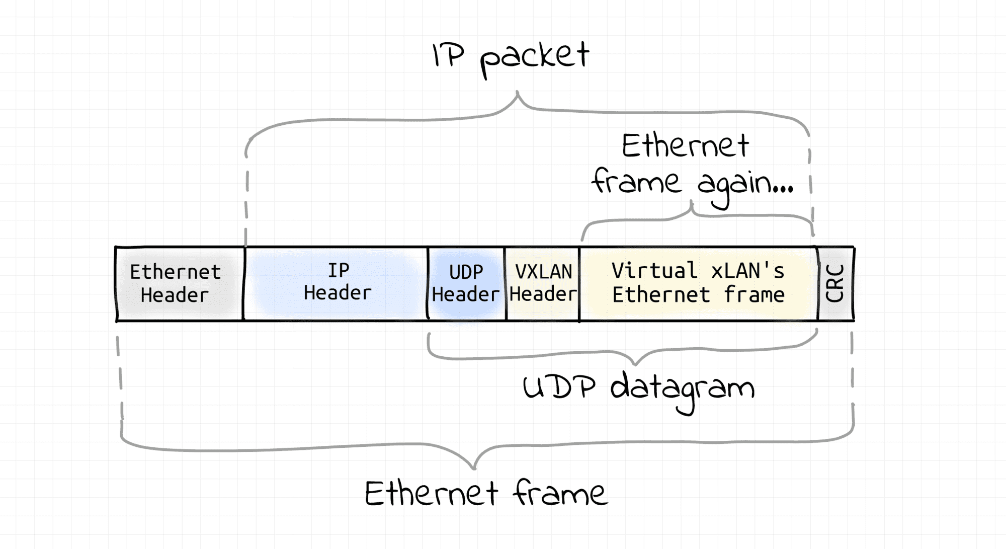
VXLAN technology also creates virtual broadcast domains out of an existing network. So, it's also sort of an overlay networking. However, it does so in a completely different fashion. Instead of relying on the underlying L2 segment capabilities, VXLAN requires that all participating nodes already have an L3 (i.e. IP) connectivity. On every VXLAN node, outgoing Ethernet frames are captured, then wrapped into UDP datagrams (encapsulated), and sent over an L3 network to the destination VXLAN node. On arrival, Ethernet frames are extracted from UDP packets (decapsulated) and injected into the destination's network interface. This technique is called tunneling. As a result, VXLAN nodes create a virtual L2 segment, hence an L2 broadcast domain.
Of course, nothing prevents us from putting all the VXLAN nodes in a single L3/L2 segment. So, then VXLAN would be just a way to overcome the limitation of VLAN on the number of networks per segment. However, usually, VXLAN is used over multiple interconnected L3 segments.
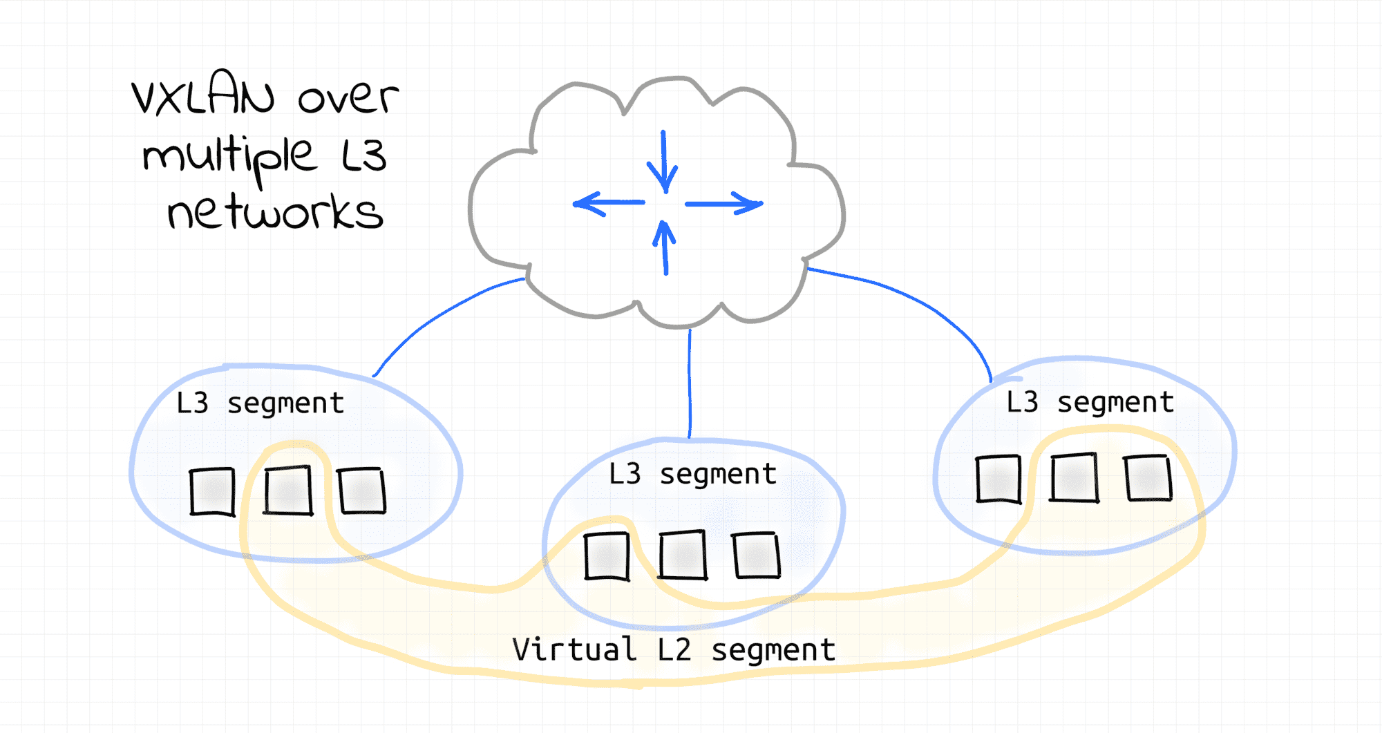
Most of the real-world VXLANs probably reside in one or few tightly connected data centers. However, since VXLAN requires only IP to IP connectivity of the participating nodes, it essentially allows one to turn arbitrary internetwork nodes into a virtualized L2 segment. While impractical, such a virtual L2 segment can be spanning multiple WANs or even a part of the Internet. This is rather mind-blowing.
From some perspective, VXLAN can be even seen as inverse to VLAN. VLAN splits a single L2 segment (and broadcast domain) into multiple non-intersecting segments that can be used to set up multiple L3 segments. VXLAN, on the contrary, can combine multiple L3 segments back into one virtual L2 segment. This is also rather mind-blowing.