Networking Lab: Setting Up a VLAN Using a Linux Bridge
Lab's Scope
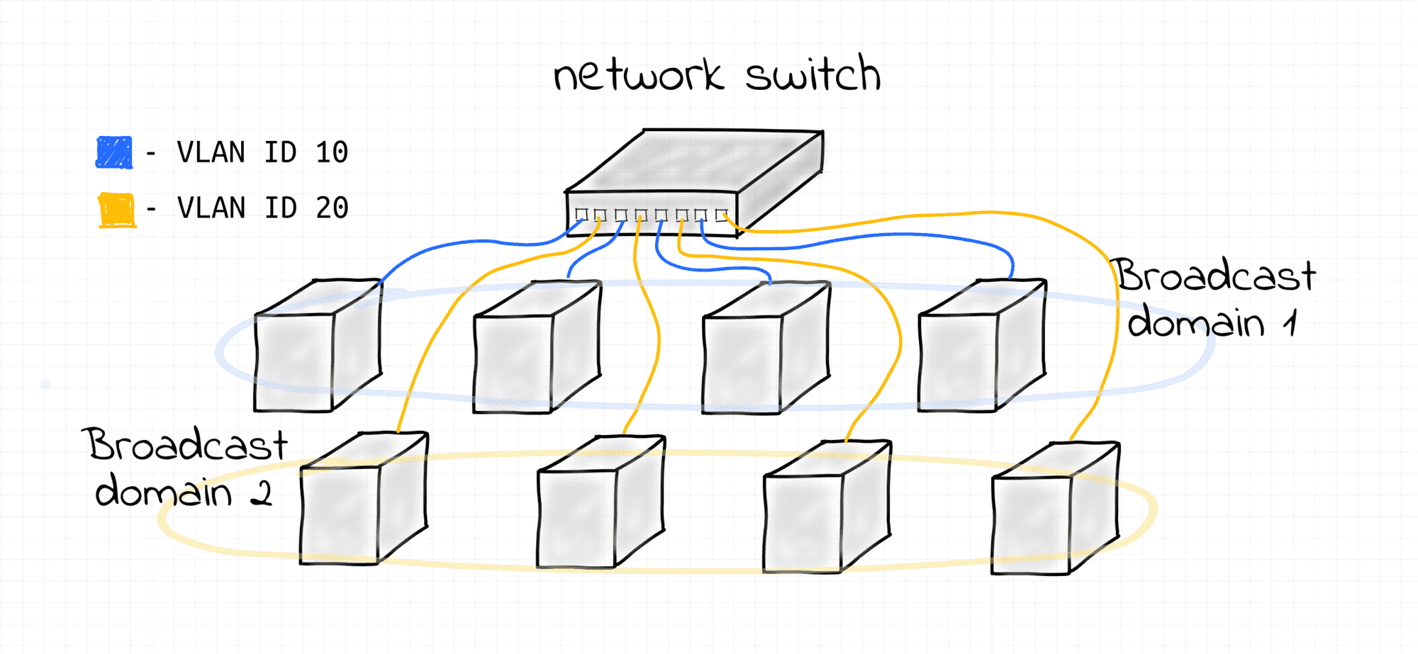
In the first lab of this course, we learned how to bridge multiple L2 segments into a larger broadcast domain. We then discovered that it's possible to configure multiple IP subnets over a single L2 broadcast domain, though this, while handy, might not be the most secure option. In this lab, we'll see how to use the native VLAN capabilities of a Linux bridge to split a single broadcast domain into multiple smaller domains, which can then be used to configure properly isolated IP subnets.
Prerequisites
We will use Linux network virtualization tools to:
- Emulate separate network nodes (via network namespaces)
- Emulate network interfaces (via veth devices)
- Emulate network switches (via bridge devices).
The playground conveniently provides a set of helper scripts to simplify the process of creating the end hosts and switches. If you use your own Linux machine to follow the course, just copy the scripts from this page.
create_bridge - creates a new network namespace with a Linux bridge device in it; the bridge is configured to filter traffic by VLAN ID via the vlan_filtering 1 option:
'create_bridge' source code
create_bridge() {
  local nsname="$1"
  local ifname="$2"

  echo "Creating bridge ${nsname}/${ifname}"

  ip netns add ${nsname}
  ip netns exec ${nsname} ip link set lo up
  ip netns exec ${nsname} ip link add ${ifname} type bridge
  ip netns exec ${nsname} ip link set ${ifname} up

  # Enable VLAN filtering on bridge.
  ip netns exec ${nsname} ip link set ${ifname} type bridge vlan_filtering 1
}
create_end_host - creates a new network namespace with a veth device in it that resides in the specified VLAN (the other end of the veth pair is connected to the bridge):
'create_end_host' source code
create_end_host() {
  local host_nsname="$1"
  local peer1_ifname="$2"
  local peer2_ifname="$2b"
  local vlan_vid="$3"
  local bridge_nsname="$4"
  local bridge_ifname="$5"

  echo "Creating end host ${host_nsname} connected to ${bridge_nsname}/${bridge_ifname} bridge (VLAN ${vlan_vid})"

  # Create end host network namespace.
  ip netns add ${host_nsname}
  ip netns exec ${host_nsname} ip link set lo up

  # Create a veth pair connecting end host and bridge namespaces.
  ip link add ${peer1_ifname} netns ${host_nsname} type veth peer \
              ${peer2_ifname} netns ${bridge_nsname}
  ip netns exec ${host_nsname} ip link set ${peer1_ifname} up
  ip netns exec ${bridge_nsname} ip link set ${peer2_ifname} up

  # Attach peer2 interface to the bridge.
  ip netns exec ${bridge_nsname} ip link set ${peer2_ifname} master ${bridge_ifname}

  # Put host into right VLAN
  ip netns exec ${bridge_nsname} bridge vlan del dev ${peer2_ifname} vid 1
  ip netns exec ${bridge_nsname} bridge vlan add dev ${peer2_ifname} vid ${vlan_vid} pvid ${vlan_vid}
}
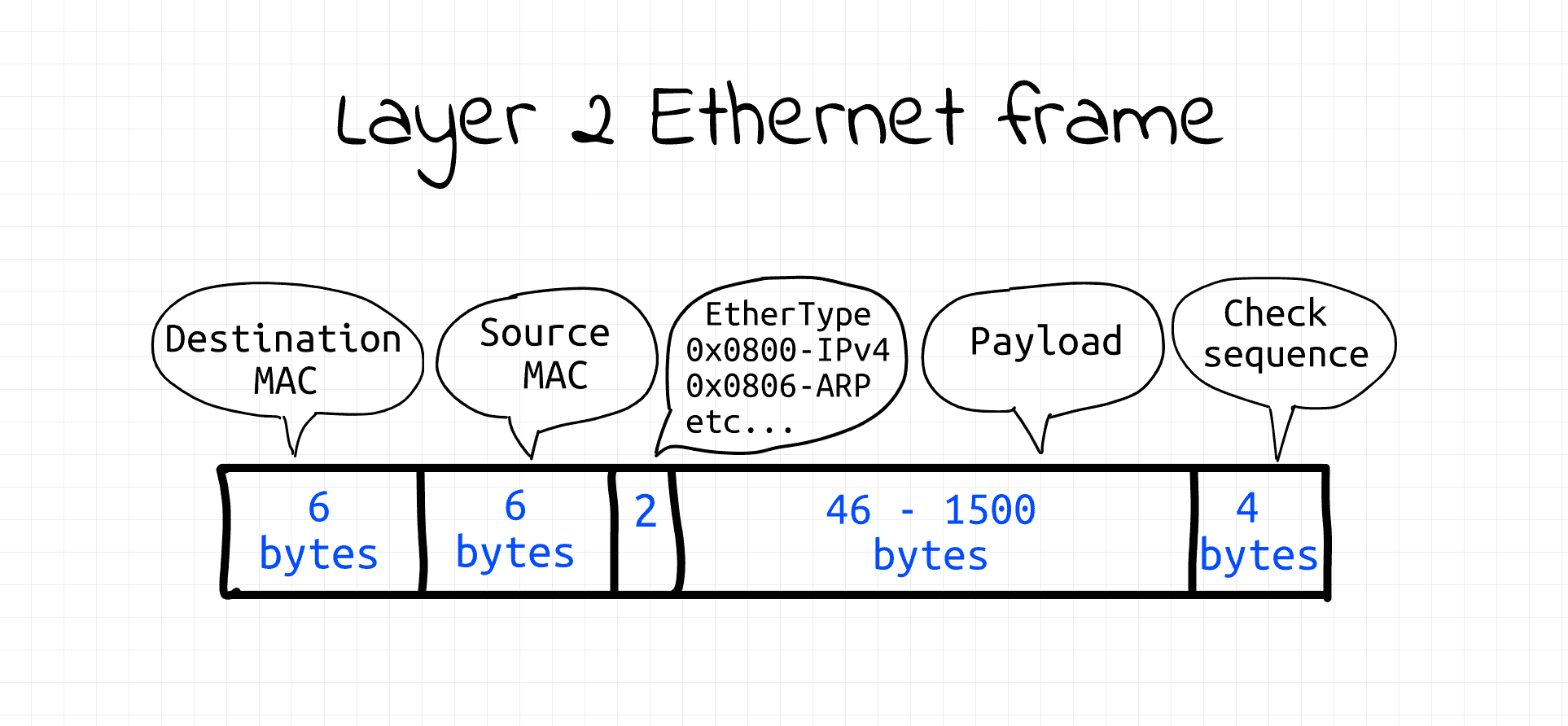
The playground also provides a tool called ethsend to manually transmit arbitrary data on the data link layer.
The tool uses packet sockets (AF_PACKET) operating in the raw mode (SOCK_RAW) to send Ethernet frames programmatically.
Luckily Ethernet frames have a fairly simple structure,
so it's fairly easy to construct them in code and then write them into the raw packet socket.
'ethsend' source code
#!/usr/bin/env python3

# Usage: ethsend eth0 ff:ff:ff:ff:ff:ff 'Hello everybody!'
#        ethsend eth0 06:e5:f0:20:af:7a 'Hello 06:e5:f0:20:af:7a!'
#
# Note: CAP_NET_RAW capability is required to use SOCK_RAW

import fcntl
import socket
import struct
import sys

def send_frame(ifname, dstmac, eth_type, payload):
  # Open raw socket and bind it to network interface.
  s = socket.socket(socket.AF_PACKET, socket.SOCK_RAW)
  s.bind((ifname, 0))

  # Get source interface's MAC address.
  info = fcntl.ioctl(s.fileno(),
                     0x8927,
                     struct.pack('256s', bytes(ifname, 'utf-8')[:15]))
  srcmac = ':'.join('%02x' % b for b in info[18:24])

  # Build Ethernet frame
  payload_bytes = payload.encode('utf-8')
  assert len(payload_bytes) <= 1500  # Ethernet MTU

  frame = human_mac_to_bytes(dstmac) + \
          human_mac_to_bytes(srcmac) + \
          eth_type + \
          payload_bytes

  # Send Ethernet frame
  return s.send(frame)

def human_mac_to_bytes(addr):
  return bytes.fromhex(addr.replace(':', ''))

def main():
  ifname = sys.argv[1]
  dstmac = sys.argv[2]
  payload = sys.argv[3]
  ethtype = b'\x7A\x05'  # arbitrary, non-reserved
  send_frame(ifname, dstmac, ethtype, payload)

if __name__ == "__main__":
  main()
CAP_NET_RAW capability is required to run the above code (or just use sudo).
How VLAN Is Implemented
To split a single L2 network segment into multiple non-intersecting sub-segments without any rewiring a technique called frame tagging is used. The Ethernet frame format is altered and an extra 4-bytes-long field is added. Among other things, it carries a VLAN ID. Frames with different VLAN IDs logically belong to different L2 broadcast domains.
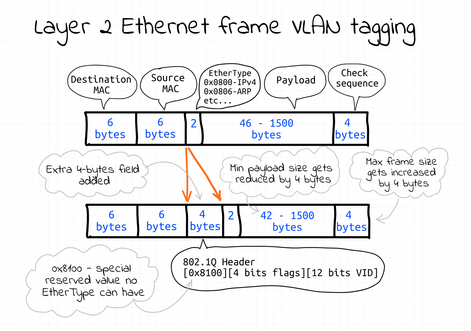
There is more than one way to tag frames. In this lab, the tagging is transparent to the end nodes and fully implemented by the bridge.
Simple VLAN Using a Linux Bridge
This example demonstrates how to configure multiple L2 broadcast domains using a single Linux bridge with multiple VLANs. Follow the steps below to reproduce it.
First, create a new network namespace (bridge1) with a bridge device (br1) in it:
create_bridge bridge1 br1
Then, create a few end hosts connected to the bridge and assigning them the same VLAN ID 10:
create_end_host host10 eth10 10 bridge1 br1
create_end_host host11 eth11 10 bridge1 br1
create_end_host host12 eth12 10 bridge1 br1
After that, create another set of end hosts connected to the same bridge but assigning them a different VLAN ID 20:
create_end_host host20 eth20 20 bridge1 br1
create_end_host host21 eth21 20 bridge1 br1
create_end_host host22 eth22 20 bridge1 br1
To demonstrate that the above hosts form two isolated broadcast domains, start monitoring their traffic.
First VLAN (using a pair of new terminal tabs):
# from host11
nsenter --net=/var/run/netns/host11 \
  tcpdump -i eth11 ether proto 0x7a05
# from host12
nsenter --net=/var/run/netns/host12 \
  tcpdump -i eth12 ether proto 0x7a05
Second VLAN (using another pair of terminal tabs):
# from host21
nsenter --net=/var/run/netns/host21 \
  tcpdump -i eth21 ether proto 0x7a05
# from host22
nsenter --net=/var/run/netns/host22 \
  tcpdump -i eth22 ether proto 0x7a05
Now, send two broadcast frames from the first hosts of each VLAN (using one more terminal tab):
# from host10
nsenter --net=/var/run/netns/host10 \
  ethsend eth10 ff:ff:ff:ff:ff:ff 'Hello VLAN 10!'
# from host20
nsenter --net=/var/run/netns/host20 \
  ethsend eth20 ff:ff:ff:ff:ff:ff 'Hello VLAN 20!'
Inspect the tcpdump output closely to check that the broadcast frames are received only by the appropriate end hosts.
Notice, that neither end hosts' interfaces, nor Ethernet sending script have to know anything about VLAN tagging. The VLAN setup in this demo is fully transparent to the end participants. The bridge assigns appropriate VLAN tags based on the frame's ingress port. But that's not the only possible way of creating VLANs. For example, VLAN tagging could have been done on the end hosts.
The key takeaway from this lab: a VLAN is an L2 construct that can be configured over an arbitrary number of bridged L2 segments partitioning a large broadcast domain into smaller ones and providing sufficient isolation for L3 subnets.
To clean things up, just remove the created network namespaces:
ip netns delete bridge1

ip netns delete host10
ip netns delete host11
ip netns delete host12

ip netns delete host20
ip netns delete host21
ip netns delete host22
Materials
- Previous lesson
- Networking Lab: L3 to L2 Segment Mapping