Networking Lab: L3 to L2 Segment Mapping
Lab's Scope
It's pretty common for an L2 broadcast domain to contain a single IP subnet. However, technically it's possible (and sometimes desirable) to configure multiple IP subnets over a single L2 segment. This lab shows how the latter case can be achieved and what are the security implications of such configuration. Understanding them will move you one step closer to grasping the idea of VLAN (and then VXLAN).
🤓 Although more complicated, configuring a single IP subnet over multiple disjoint L2 segments is also possible using the Proxy ARP technique. However, it's beyond the scope of this course.
Prerequisites
We will use Linux network virtualization tools to:
- Emulate separate network nodes (via network namespaces)
- Emulate network interfaces (via veth devices)
- Emulate network switches (via bridge devices).
The playground conveniently provides a set of helper scripts to simplify the process of creating the end hosts and switches. If you use your own Linux machine to follow the course, just copy the scripts from this page.
create_bridge - creates a new network namespace with a Linux bridge device in it:
'create_bridge' source code
create_bridge() {
  local nsname="$1"
  local ifname="$2"

  echo "Creating bridge ${nsname}/${ifname}"

  ip netns add ${nsname}
  ip netns exec ${nsname} ip link set lo up
  ip netns exec ${nsname} ip link add ${ifname} type bridge
  ip netns exec ${nsname} ip link set ${ifname} up
}
create_end_host - creates a new network namespace with a veth device and assigns an IP address to it (the other end of the veth pair is connected to the specified bridge in another namespace):
'create_end_host' source code
create_end_host() {
  local host_nsname="$1"
  local peer1_ifname="$2"
  local peer2_ifname="$2b"
  local peer1_ifaddr="$3"
  local bridge_nsname="$4"
  local bridge_ifname="$5"

  echo "Creating end host ${host_nsname} ${peer1_ifaddr} connected to ${bridge_nsname}/${bridge_ifname} bridge"

  # Create end host network namespace.
  ip netns add ${host_nsname}
  ip netns exec ${host_nsname} ip link set lo up

  # Create a veth pair connecting end host and bridge namespaces.
  ip link add ${peer1_ifname} netns ${host_nsname} type veth peer \
              ${peer2_ifname} netns ${bridge_nsname}
  ip netns exec ${host_nsname} ip link set ${peer1_ifname} up
  ip netns exec ${bridge_nsname} ip link set ${peer2_ifname} up

  # Setting host's IP address.
  ip netns exec ${host_nsname} ip addr add ${peer1_ifaddr} dev ${peer1_ifname}

  # Attach peer2 interface to the bridge.
  ip netns exec ${bridge_nsname} ip link set ${peer2_ifname} master ${bridge_ifname}
}
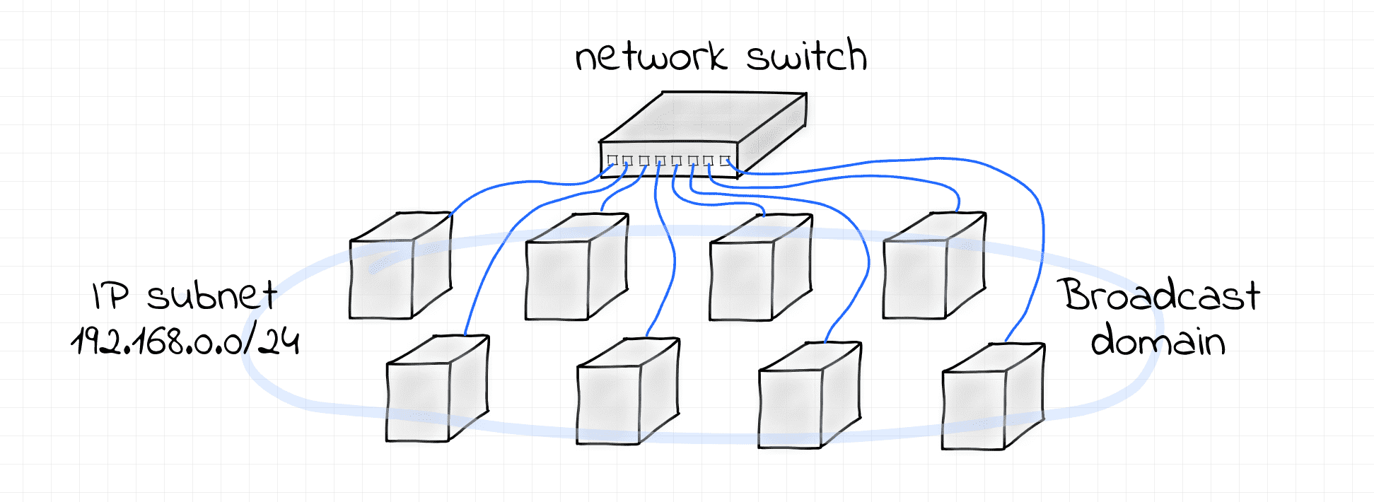
One L2 Segment, One IP Subnet
This example demonstrates the simplest possible scenario -
an IP subnet 192.168.0.0/24 configured over a single L2 broadcast domain formed by a Linux bridge.
Follow the steps below to reproduce it.
Pro Tip: You can use the labctl ssh command to follow the lab instructions from your favorite local terminal.
First, create a bridge device for the end hosts to connect to:
create_bridge bridge1 br1
Next, create the end hosts:
create_end_host host1 eth1 '192.168.0.1/24' bridge1 br1
create_end_host host2 eth2 '192.168.0.2/24' bridge1 br1
create_end_host host3 eth3 '192.168.0.3/24' bridge1 br1
Why the interfaces are configured with both IP address and network mask?
Notice that the interfaces are configured with the IP addresses and the additional network mask.
Having a network mask specified allows the Linux kernel to deduce the route to the 192.168.0.0/24 network automatically.
Check it out:
# host1
nsenter --net=/var/run/netns/host1 \
  ip route show
192.168.0.0/24 dev eth1 proto kernel scope link src 192.168.0.1
# host2
nsenter --net=/var/run/netns/host2 \
  ip route show
192.168.0.0/24 dev eth2 proto kernel scope link src 192.168.0.2
# host3
nsenter --net=/var/run/netns/host3 \
  ip route show
192.168.0.0/24 dev eth3 proto kernel scope link src 192.168.0.3
These routes have a link scope, i.e. packets destined to the 192.168.0.0/24 network won't need to go to a router.
Instead, they can be delivered using the physical link these nodes are directly connected to.
It's time to check the L3 connectivity between the hosts.
Using a separate terminal tab, start monitoring the traffic on the eth2 interface of the host2 node:
# from host2
nsenter --net=/var/run/netns/host2 \
  tcpdump -i eth2
In another terminal tab, start monitoring the traffic on the eth3 interface of the host3 node:
# from host3
nsenter --net=/var/run/netns/host3 \
  tcpdump -i eth3
Finally, using one more terminal tab, ping the host2 from the host1:
nsenter --net=/var/run/netns/host1 \
  ping 192.168.0.2
Inspect the tcpdump output of the host2 and host3 nodes closely.
You should see the host1 <-> host2 traffic flowing but also some activity in the host3's tab.
This is because the point-to-point communication via IP relies on the underlying L2 communication means:
direct MAC addressability and broadcasting via the special FF:FF:FF:FF:FF:FF destination address.
To clean things up, just remove the created network namespaces:
ip netns delete bridge1
ip netns delete host1
ip netns delete host2
ip netns delete host3
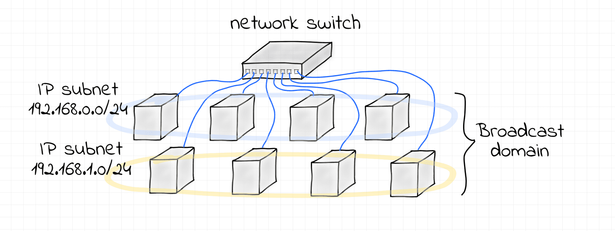
One L2 Segment, Multiple IP Subnets
This is a slightly more complex scenario -
two non-intersecting IP subnets 192.168.0.0/24 and 192.168.1.0/24 configured over a single L2 broadcast domain formed by a Linux bridge.
Again, starting with creating a bridge device for the end hosts to connect to:
create_bridge bridge2 br2
Next, configuring the first IP subnet 192.168.0.0/24:
# subnet I
create_end_host host10 eth10 192.168.0.10/24 bridge2 br2
create_end_host host11 eth11 192.168.0.11/24 bridge2 br2
create_end_host host12 eth12 192.168.0.12/24 bridge2 br2
...and the second IP subnet 192.168.1.0/24:
# subnet II
create_end_host host20 eth20 192.168.1.20/24 bridge2 br2
create_end_host host21 eth21 192.168.1.21/24 bridge2 br2
create_end_host host22 eth22 192.168.1.22/24 bridge2 br2
Now let's test the connectivity between the hosts from different subnets. Using separate terminal tabs, start monitoring the traffic on all but the first nodes of every subnet:
# from host11
nsenter --net=/var/run/netns/host11 \
  tcpdump -i eth11 arp or icmp
# from host12
nsenter --net=/var/run/netns/host12 \
  tcpdump -i eth12 arp or icmp
# from host21
nsenter --net=/var/run/netns/host21 \
  tcpdump -i eth21 arp or icmp
# from host22
nsenter --net=/var/run/netns/host22 \
  tcpdump -i eth22 arp or icmp
...and using two more terminal tabs,
generate some intra-subnet traffic from the host10 and host20 nodes correspondingly:
# from host10 to host12
nsenter --net=/var/run/netns/host10 \
  ping 192.168.0.12
# from host20 to host22
nsenter --net=/var/run/netns/host20 \
  ping 192.168.1.22
Inspect the traffic captured by the tcpdump processes.
Notice how Ethernet frames (in particular, ARP requests) that belong to one subnet are actually visible to the hosts from another subnet.
First of all, the above example proves that it's indeed possible to have multiple IP subnets over a shared L2 segment. However, it also shows that there is a lack of isolation and the traffic destined to one of the subnets is visible to the nodes from another subnet. It happens because nodes from both subnets share the same L2 broadcast domain. This may be undesirable, in particular, due to security concerns (see ARP spoofing). In such a situation, configuring multiple VLANs on the shared bridge can bring the proper isolation.
To clean up, just remove the created network namespaces:
ip netns delete bridge2

ip netns delete host10
ip netns delete host11
ip netns delete host12

ip netns delete host20
ip netns delete host21
ip netns delete host22
- Previous lesson
- Networking Lab: Ethernet Broadcast Domains