Networking Lab: Ethernet Broadcast Domains
Lab's Scope
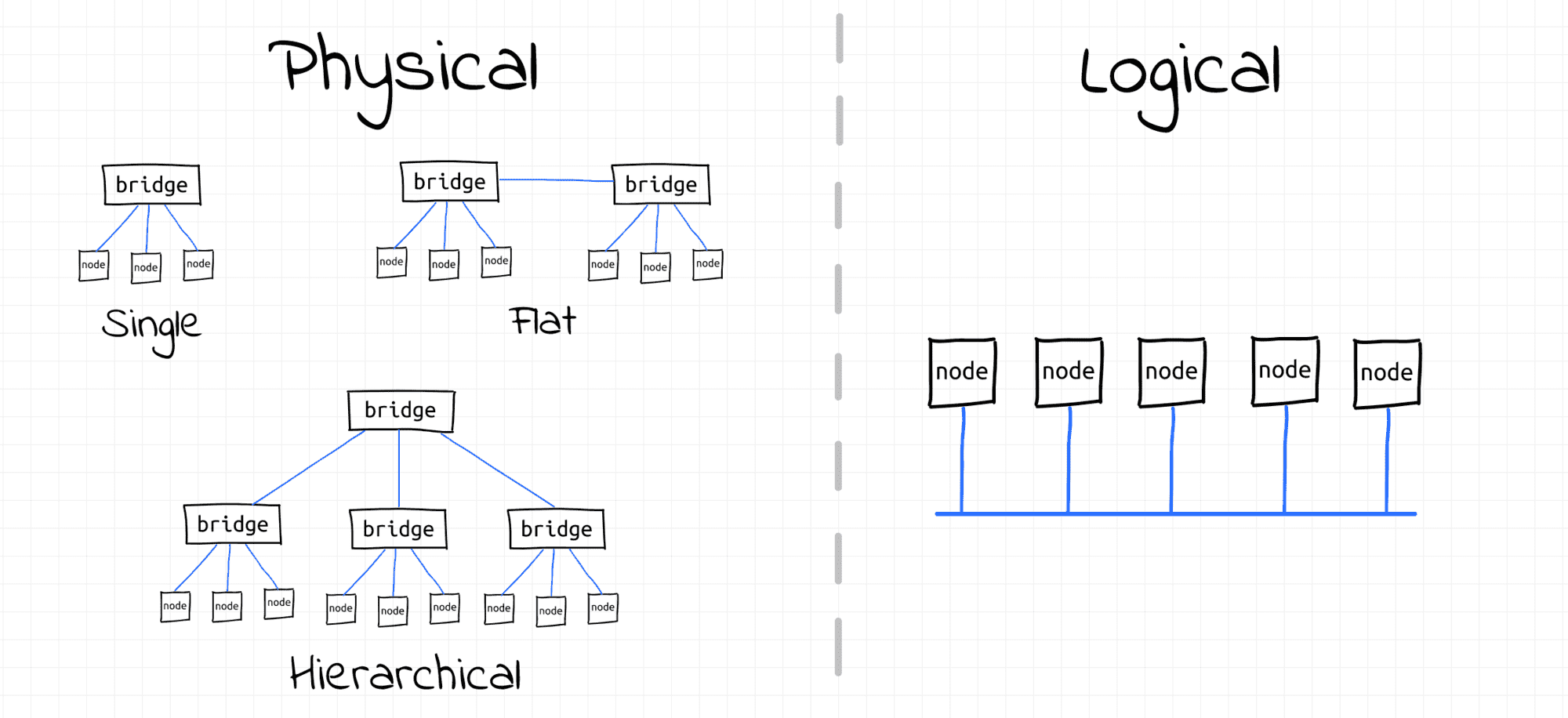
In Ethernet, all nodes of one L2 segment form a broadcast domain. Such nodes should be able to communicate using their L2 addresses (MAC) or by broadcasting frames. A broadcast domain is a logical division of a computer network. Multiple physical (L1) segments can be bridged to form a single broadcast domain. Multiple L2 segments can also be bridged to create a bigger broadcast domain. In this lab, we will practice creating broadcast domains with varying levels of complexity.
Prerequisites
We will use Linux network virtualization tools to:
- Emulate separate network nodes (via network namespaces)
- Emulate network interfaces (via veth devices)
- Emulate network switches (via bridge devices).
The playground conveniently provides a set of helper scripts to simplify the process of creating the end hosts and switches. If you use your own Linux machine to follow the course, just copy the scripts from this page.
create_bridge - creates a new network namespace with a Linux bridge device in it:
'create_bridge' source code
create_bridge() {
  local nsname="$1"
  local ifname="$2"

  echo "Creating bridge ${nsname}/${ifname}"

  ip netns add ${nsname}
  ip netns exec ${nsname} ip link set lo up
  ip netns exec ${nsname} ip link add ${ifname} type bridge
  ip netns exec ${nsname} ip link set ${ifname} up
}
create_end_host - creates a new network namespace with a veth device in it (the other end of the veth pair is connected to the specified bridge in another namespace):
'create_end_host' source code
create_end_host() {
  local host_nsname="$1"
  local peer1_ifname="$2"
  local peer2_ifname="$2b"
  local bridge_nsname="$3"
  local bridge_ifname="$4"

  echo "Creating end host ${host_nsname} connected to ${bridge_nsname}/${bridge_ifname} bridge"

  # Create end host network namespace.
  ip netns add ${host_nsname}
  ip netns exec ${host_nsname} ip link set lo up

  # Create a veth pair connecting end host and bridge namespaces.
  ip link add ${peer1_ifname} netns ${host_nsname} type veth peer \
              ${peer2_ifname} netns ${bridge_nsname}
  ip netns exec ${host_nsname} ip link set ${peer1_ifname} up
  ip netns exec ${bridge_nsname} ip link set ${peer2_ifname} up

  # Attach peer2 interface to the bridge.
  ip netns exec ${bridge_nsname} ip link set ${peer2_ifname} master ${bridge_ifname}
}
connect_bridges - interconnects two Linux bridges (switches) potentially residing in different network namespaces using an auxiliary veth pair:
'connect_bridges' source code
connect_bridges() {
  local bridge1_nsname="$1"
  local bridge1_ifname="$2"
  local bridge2_nsname="$3"
  local bridge2_ifname="$4"
  local peer1_ifname="veth_${bridge2_ifname}"
  local peer2_ifname="veth_${bridge1_ifname}"

  echo "Connecting bridge ${bridge1_nsname}/${bridge1_ifname} to ${bridge2_nsname}/${bridge2_ifname} bridge using veth pair"

  # Create veth pair.
  ip link add ${peer1_ifname} netns ${bridge1_nsname} type veth peer \
              ${peer2_ifname} netns ${bridge2_nsname}
  ip netns exec ${bridge1_nsname} ip link set ${peer1_ifname} up
  ip netns exec ${bridge2_nsname} ip link set ${peer2_ifname} up

  # Connect bridges.
  ip netns exec ${bridge1_nsname} ip link set ${peer1_ifname} master ${bridge1_ifname}
  ip netns exec ${bridge2_nsname} ip link set ${peer2_ifname} master ${bridge2_ifname}
}
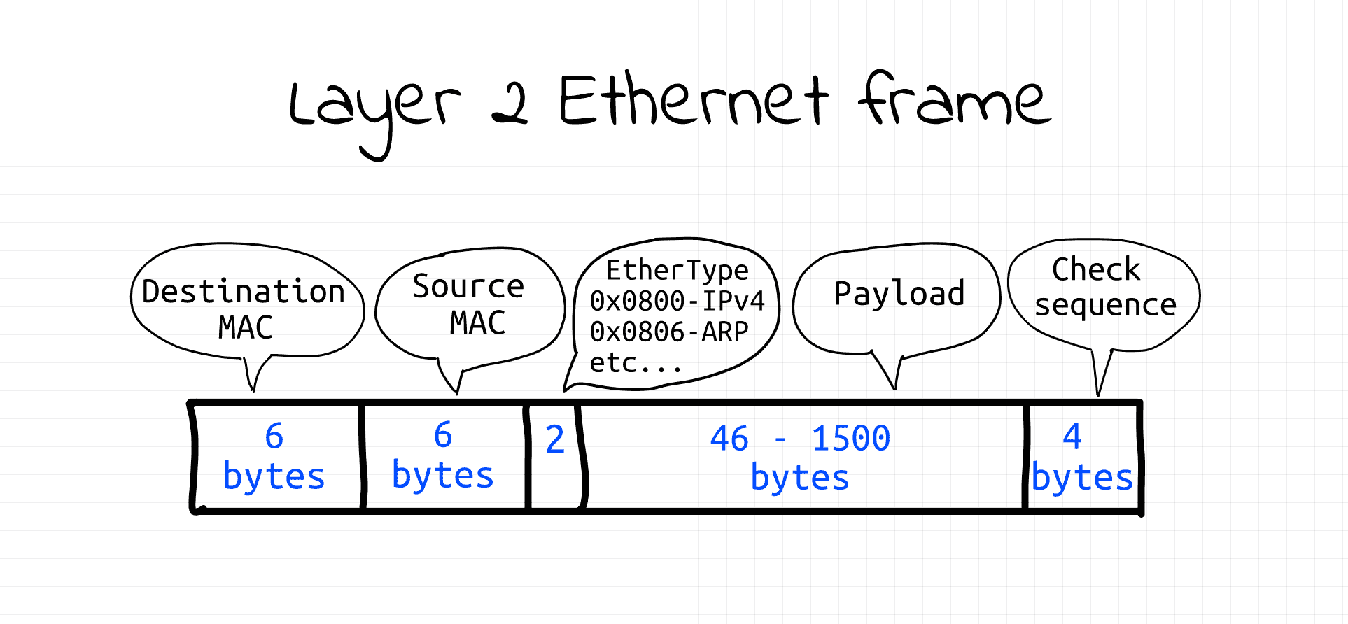
The playground also provides a tool called ethsend to manually transmit arbitrary data on the data link layer.
The tool uses packet sockets (AF_PACKET) operating in the raw mode (SOCK_RAW) to send Ethernet frames programmatically.
Luckily Ethernet frames have a fairly simple structure,
so it's fairly easy to construct them in code and then write them into the raw packet socket.
'ethsend' source code
#!/usr/bin/env python3

# Usage: ethsend eth0 ff:ff:ff:ff:ff:ff 'Hello everybody!'
#        ethsend eth0 06:e5:f0:20:af:7a 'Hello 06:e5:f0:20:af:7a!'
#
# Note: CAP_NET_RAW capability is required to use SOCK_RAW

import fcntl
import socket
import struct
import sys

def send_frame(ifname, dstmac, eth_type, payload):
  # Open raw socket and bind it to network interface.
  s = socket.socket(socket.AF_PACKET, socket.SOCK_RAW)
  s.bind((ifname, 0))

  # Get source interface's MAC address.
  info = fcntl.ioctl(s.fileno(),
                     0x8927,
                     struct.pack('256s', bytes(ifname, 'utf-8')[:15]))
  srcmac = ':'.join('%02x' % b for b in info[18:24])

  # Build Ethernet frame
  payload_bytes = payload.encode('utf-8')
  assert len(payload_bytes) <= 1500  # Ethernet MTU

  frame = human_mac_to_bytes(dstmac) + \
          human_mac_to_bytes(srcmac) + \
          eth_type + \
          payload_bytes

  # Send Ethernet frame
  return s.send(frame)

def human_mac_to_bytes(addr):
  return bytes.fromhex(addr.replace(':', ''))

def main():
  ifname = sys.argv[1]
  dstmac = sys.argv[2]
  payload = sys.argv[3]
  ethtype = b'\x7A\x05'  # arbitrary, non-reserved
  send_frame(ifname, dstmac, ethtype, payload)

if __name__ == "__main__":
  main()
⚠️ CAP_NET_RAW capability is required to run the above code (or just use sudo).
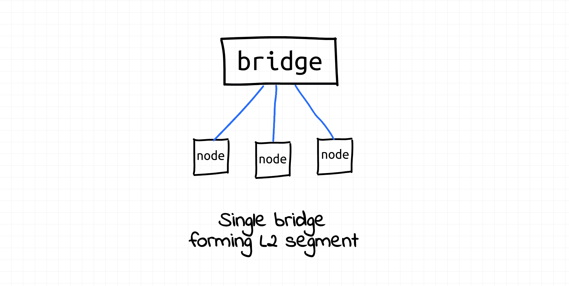
Multiple Hosts, One Network Switch
This example demonstrates the simplest possible scenario - a group of network hosts connected to a shared switch. Follow the steps below to reproduce it.
Pro Tip: You can use the labctl ssh command to follow the lab instructions from your favorite local terminal.
Create a new network namespace (bridge1) with a bridge device (br1) in it:
create_bridge bridge1 br1
Create three hosts connected to the br1 bridge:
create_end_host host1 eth1 bridge1 br1
create_end_host host2 eth2 bridge1 br1
create_end_host host3 eth3 bridge1 br1
In a separate terminal, start monitoring network traffic on host2's eth2 interface:
# from host2
nsenter --net=/var/run/netns/host2 \
  tcpdump -i eth2 ether proto 0x7a05  # i.e. Ethernet
In another terminal, start monitoring network traffic on host3's eth3 interface:
# from host3
nsenter --net=/var/run/netns/host3 \
  tcpdump -i eth3 ether proto 0x7a05  # i.e. Ethernet
Now, using one more terminal,
send a broadcast frame from host1 to all hosts in the same broadcast domain leveraging the special MAC address FF:FF:FF:FF:FF:FF:
# from host1 to all hosts
nsenter --net=/var/run/netns/host1 \
  ethsend eth1 ff:ff:ff:ff:ff:ff 'Hello all!'
Check the tcpdump output in the host2 and host3 terminals -
do you see the 'Hello all!' message from host1?
Finally, to demonstrate that hosts connected to the same switch can also directly communicate with each other using their MAC addresses,
send Ethernet frames from host1 individually to host2 and then to host3:
ETH2_MAC=$(ip netns exec host2 ip link show eth2 | grep ether | awk '{print $2}')

# from host1 to host2
nsenter --net=/var/run/netns/host1 \
  ethsend eth1 ${ETH2_MAC} "Hello host2!"
ETH3_MAC=$(ip netns exec host3 ip link show eth3 | grep ether | awk '{print $2}')

# from host1 to host3
nsenter --net=/var/run/netns/host1 \
  ethsend eth1 ${ETH3_MAC} "Hello host3!"
To clean things up, just remove the created network namespaces:
ip netns delete bridge1
ip netns delete host1
ip netns delete host2
ip netns delete host3
💡 By the way, this lab also demonstrates that hosts on a single L2 segment don't technically need any L3 configuration (assigning IP addresses or setting routing rules) to communicate with each other.
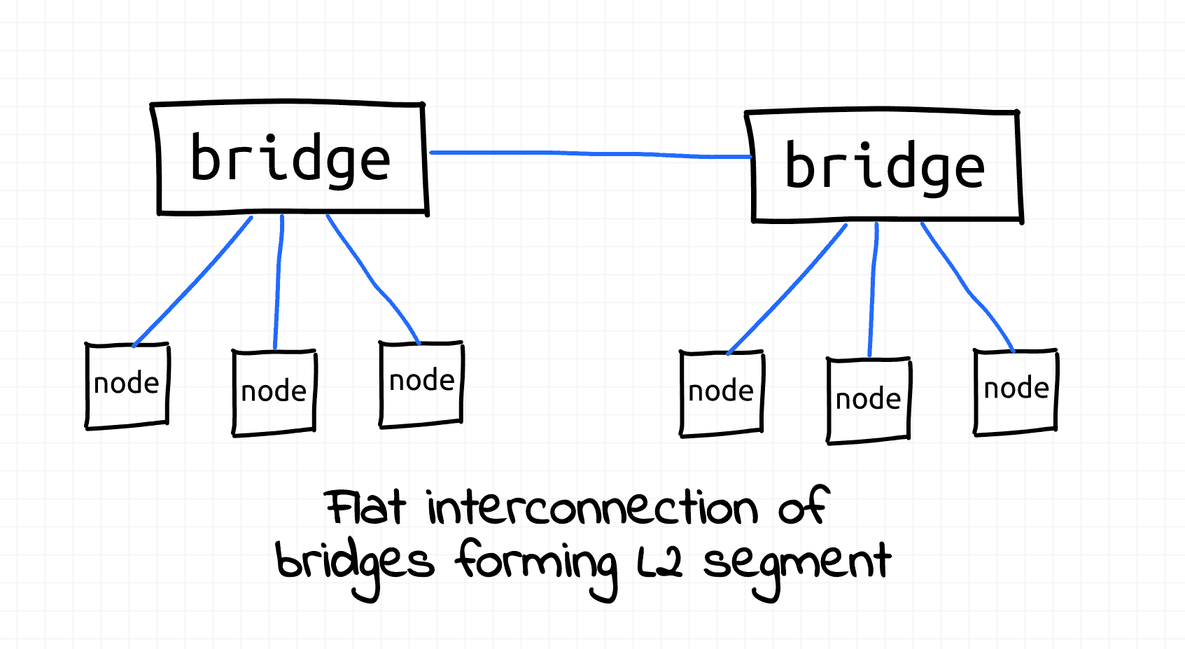
Two Interconnected Network Switches
The number of nodes connected to a single switch is limited by the number of available physical ports. Even the Linux bridge (a virtual switch) has a limitation of 1024 ports. To overcome this limitation, when the required number of nodes in the broadcast domain exceeds the number of available physical ports on a single switch, multiple switches get interconnected to extend the broadcast domain.
In this example we'll demonstrate that multiple interconnected network switches (bridges) still form a single broadcast domain:
First, create two disjoint network segments:
create_bridge bridge10 br10
create_end_host host10 eth10 bridge10 br10
create_end_host host11 eth11 bridge10 br10
create_bridge bridge20 br20
create_end_host host20 eth20 bridge20 br20
create_end_host host21 eth21 bridge20 br20
Then, connect the two bridges with a patch cord (veth pair):
connect_bridges bridge10 br10 bridge20 br20
To demonstrate that all hosts now form a single broadcast domain, start monitoring traffic on all but the first host of the first switch.
First switch, second host (in a separate terminal):
# from host11
nsenter --net=/var/run/netns/host11 \
  tcpdump -i eth11 ether proto 0x7a05
Second switch, first host (in a separate terminal):
# from host20
nsenter --net=/var/run/netns/host20 \
  tcpdump -i eth20 ether proto 0x7a05
Second switch, second host (in a separate terminal):
# from host21
nsenter --net=/var/run/netns/host21 \
  tcpdump -i eth21 ether proto 0x7a05
Finally, using one more terminal, send a broadcast message from the first host of the first switch:
# from host10
nsenter --net=/var/run/netns/host10 \
  ethsend eth10 ff:ff:ff:ff:ff:ff 'Hello all!'
Notice that all hosts receive the broadcast message. Thus, from the nodes' standpoint (logically) there is no difference between being connected to a single switch (bridge) or multiple interconnected switches. They still form one flat L2 segment and a single broadcast domain.
To clean things up, just remove the created network namespaces:
ip netns delete bridge10
ip netns delete host10
ip netns delete host11

ip netns delete bridge20
ip netns delete host20
ip netns delete host21
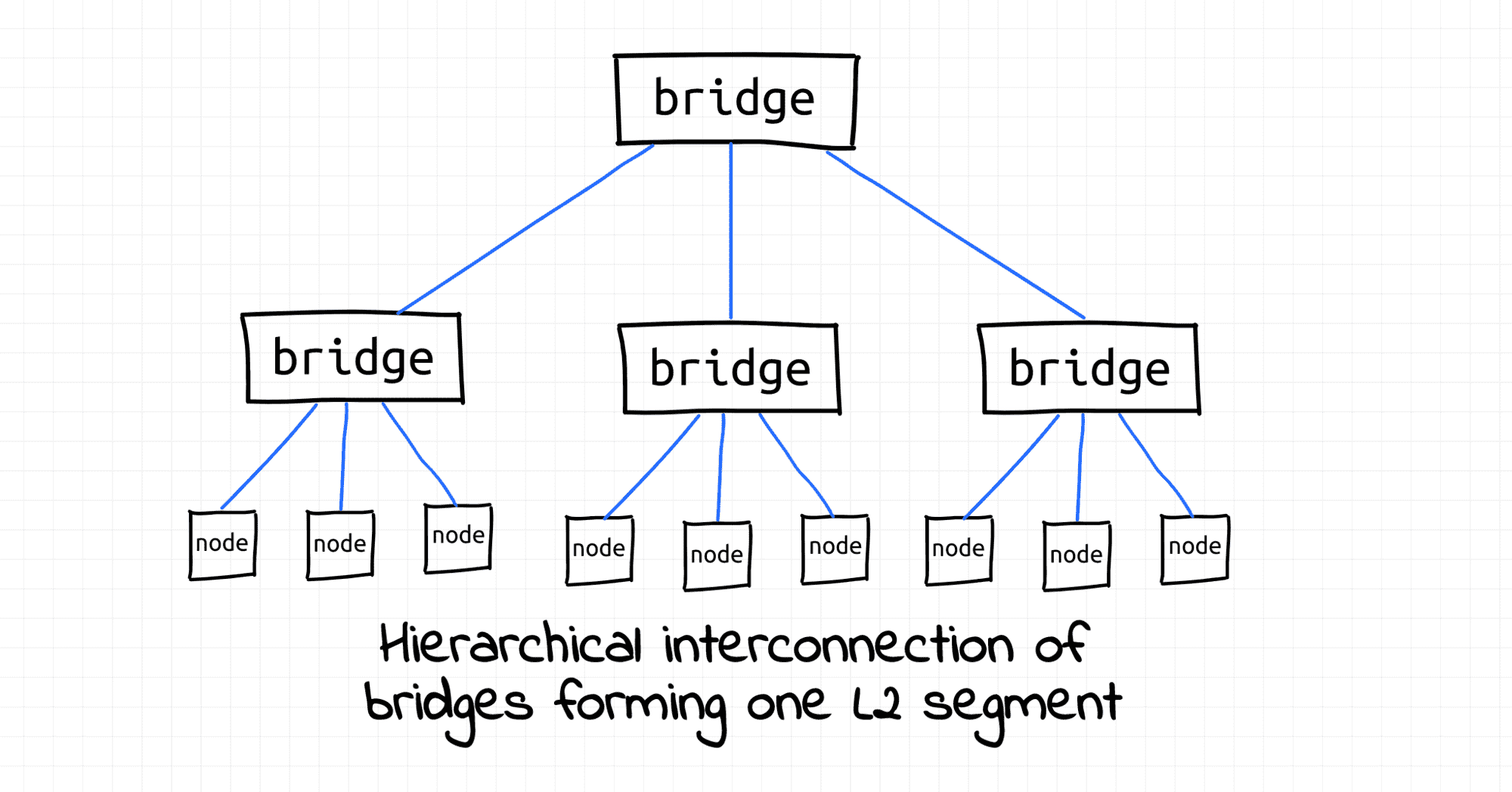
Hierarchical Internetworking (Simplified)
In a big enough setup, a flat interconnection of switches will lead to a high amount of transit traffic, so a hierarchical interconnection of switches is used to provide better performance.
In this example we'll show that multi-level interconnection of switches also forms a single broadcast domain:
First, create two disjoint network segments:
# Lower-layer segment I
create_bridge bridge100 br100
create_end_host host100 eth100 bridge100 br100
create_end_host host101 eth101 bridge100 br100
# Lower-layer segment II
create_bridge bridge200 br200
create_end_host host200 eth200 bridge200 br200
create_end_host host201 eth201 bridge200 br200
Then, create a higher-layer switch:
# Higher-layer switch
create_bridge bridge300 br300
...and connect the lower-layer switches to it:
# Connect both lower-layer switches to higher layer switch
connect_bridges bridge100 br100 bridge300 br300
connect_bridges bridge200 br200 bridge300 br300
To demonstrate that all hosts now form a single broadcast domain, start monitoring traffic on all but the first host of the first lower-layer switch.
First lower-layer switch, second host (in a separate terminal):
# from host101
nsenter --net=/var/run/netns/host101 \
  tcpdump -i eth101 ether proto 0x7a05
Second lower-layer switch, first host (in a separate terminal):
# from host200
nsenter --net=/var/run/netns/host200 \
  tcpdump -i eth200 ether proto 0x7a05
Second lower-layer switch, second host (in a separate terminal):
# from host201
nsenter --net=/var/run/netns/host201 \
  tcpdump -i eth201 ether proto 0x7a05
Finally, using one more terminal, send a broadcast message from the first host of the first lower-layer switch:
nsenter --net=/var/run/netns/host100 \
  ethsend eth100 ff:ff:ff:ff:ff:ff 'Hello all!'
All three terminals should now show the same broadcast message.
Once again, logically there is no difference between flat and hierarchical interconnections:
To clean things up, just remove the created network namespaces:
ip netns delete bridge100
ip netns delete host100
ip netns delete host101

ip netns delete bridge200
ip netns delete host200
ip netns delete host201

ip netns delete bridge300
Materials
- Previous lesson
- Bridge vs. Switch: Takeaways from a Real Data Center Tour
- Next lesson
- Networking Lab: L3 to L2 Segment Mapping