Building an eBPF/XDP L2 Direct Server Return Load Balancer from Scratch

In the previous tutorial, we built a NAT-based XDP load balancer. One nice thing about that setup was that both requests and responses passed through the load balancer, making it easier to apply custom network policies or perform packet inspection in both directions.
However, this approach isn’t always optimal. Because the load balancer handles traffic in both directions, it consumes more resources and can become a bottleneck. After all, the backend could just respond directly to the client instead of routing the reply back through the load balancer.
Not to mention, inbound traffic is usually much smaller than outbound traffic. A short search query or initial AI prompt is only a few bytes, while the response (search results or an AI completion) is often much larger.
But an even bigger problem is that the backend isn’t really aware of which client made the request, since the NAT load balancer rewrote the packet headers. Meaning, if the backend wants to maintain per-user sessions, or log requests by source IP, it can’t really do that.
To overcome these downsides, Direct Server Return (DSR) concept was introduced.
There are several DSR (Direct Server Return) implementations — including Layer 2 DSR, IP-in-IP, and GRE-based DSR — as well as some unique variations that leverage fields like IP or TCP header fields.
This tutorial focuses on Layer 2 DSR (with Simple Hashing) using eBPF/XDP, while other approaches will be covered in upcoming labs.
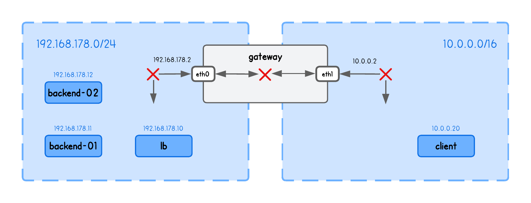
This playground has a network topology with five nodes on two different networks:
lbin network192.168.178.10/24backend-01in network192.168.178.11/24backend-02in network192.168.178.12/24clientin network10.0.0.20/16gatewaybetween networks192.168.178.2/24and10.0.0.2/16
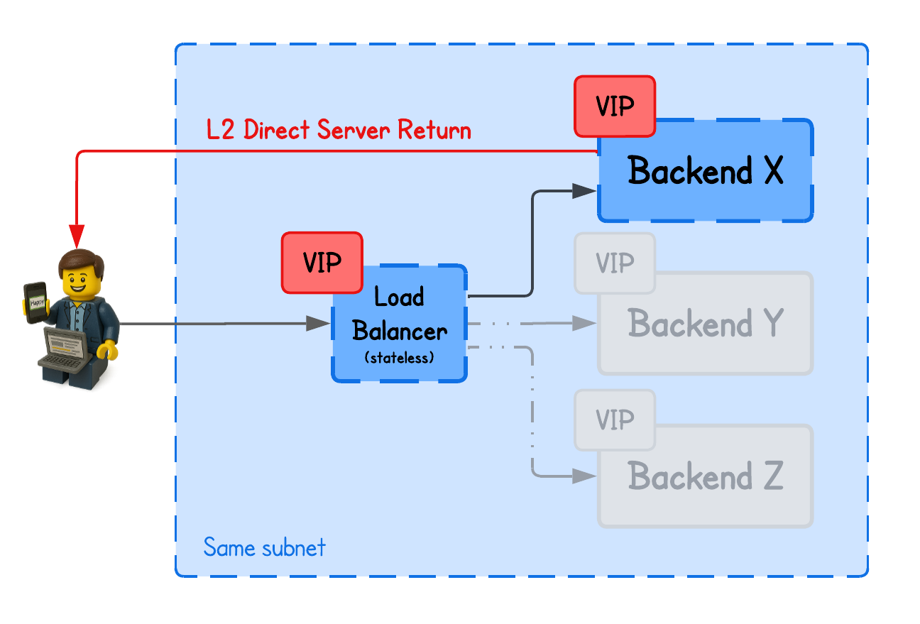
DSR L2 Load Balancing
Unlike NAT-based load balancing, DSR preserves the original client IP and allows the backend to respond directly to the client, bypassing the load balancer on the return path.
To understand how this is possible, we need to answer three questions:
- How does the backend see the client IP if the packet went through the load balancer?
- How does the backend know which client to respond to?
- How do we ensure the client receives the response from the same IP it sent the request to?
In short, L2 DSR achieves this by rewriting only the MAC addresses of packets at the load balancer, keeping the IP header unchanged, and relying on a virtual IP between the load balancer and backend servers.
Let’s take it slow...
Virtual IP (VIP)
In any network setup, whenever a client sends a request to a specific endpoint, it expects the response to come from that same IP address. If the reply comes from a different IP, the client’s network stack assumes an error and drops the packet.
And if you remember the NAT-based load balancing, this creates a problem since the client’s request always passed through the load balancer, which forwarded it to a backend node that has a different IP.
To address this, both the load balancer and the backend nodes need to share the same IP, ensuring the client always sees responses as coming from the same address it originally contacted.
This "shared IP" is called Virtual IP (VIP).
💡 Unlike physical IPs, a Virtual IP (VIP) is not bound to a specific interface or node. Instead, it's a shared address used by multiple nodes to handle traffic for the same service.
Confusing, right? Read along.
To set this up in our playground, configure the VIP on the load balancer’s (lb tab) main interface (eth0):
sudo ip addr add 192.168.178.15/32 dev eth0 # 192.168.178.15 is our VIP for this example
And, on both backends (backend-01 and backend-02 tabs), configure the VIP on the loopback interface (lo):
sudo ip addr add 192.168.178.15/32 dev lo # 192.168.178.15 is our VIP for this example
But wait — two nodes with the same IP? Wouldn't that confuse the client or gateway, seeing both advertise the same address?
Exactly — that’s why we assign the VIP to the lo interface on backend nodes. We don’t want the backends to advertise the virtual IP (via ARP).
In other words, no one in the network should know the VIP exists on the backends; otherwise, clients could bypass the load balancer and connect directly.
To prevent backend nodes from responding to ARP requests (i.e., advertising) for the VIP address on the lo interface, run the following on each backend node (backend-01 and backend-02 tabs):
# Only reply to ARP requests if the target IP is assigned to the interface
# that received the request (prevents advertising the VIP on eth0)
sudo sysctl -w net.ipv4.conf.eth0.arp_ignore=1

# When sending ARP requests, use only addresses assigned to the outgoing interface
# (prevents the node from leaking the VIP as a source IP in ARP)
sudo sysctl -w net.ipv4.conf.eth0.arp_announce=2
Then what’s the point of the virtual IP, and how does the load balancer reach the backends if that IP "isn’t advertised"?
The cool part is that load balancer doesn't really have to know the VIP exists on the backend nodes.
It only needs the backend’s MAC address to forward packets at Layer 2. When a backend receives the packet, it decapsulates it and recognizes the virtual IP as its own (configured on the lo interface), even though that IP is never advertised on the network.
This is also why this concept is called Layer 2 DSR—the load balancer reaches backend nodes using only their MAC addresses, which wouldn’t work if the backends were in a different (L2) network.
Here's an image to illustrate this concept.
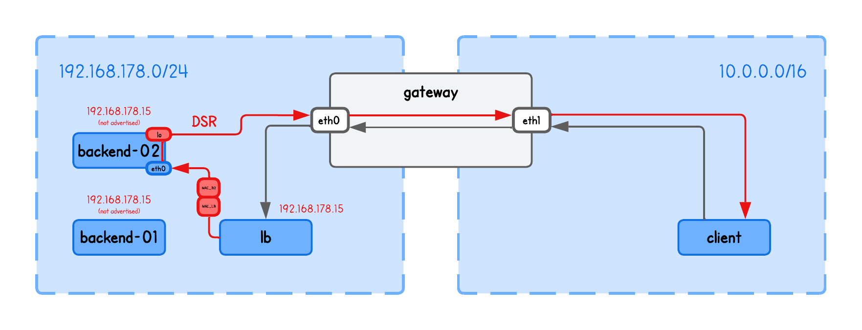
In other words, when a client connects to the VIP, the:
- Gateway routes the traffic to the load balancer
- Load balancer then forwards the packet to a backend by rewriting the (source and) destination MAC address
- Backend has the VIP configured on its
lointerface, it recognizes the packet as its own and processes it
Verify the setup
You can verify this by checking that 192.168.178.15 maps to the load balancer’s MAC address in the ARP table on the gateway.
Run the following on the gateway tab:
ip neigh show
192.168.178.15 dev eth0 lladdr XX:XX:XX:XX:XX:XX REACHABLE
If there’s no entry for 192.168.178.15, populate it with:
sudo ping -c1 192.168.178.15
Now, verify that the MAC address (XX:XX:XX:XX:XX:XX) matches the load balancer’s MAC address (from the lb tab) using:
ip link show eth0
2: eth0: <BROADCAST,MULTICAST,UP,LOWER_UP> mtu 1500 qdisc fq_codel state UP mode DEFAULT group default qlen 1000
    link/ether XX:XX:XX:XX:XX:XX brd ff:ff:ff:ff:ff:ff
We're almost ready for the next step, but just like with the NAT load balancer, we first need to enable IP forwarding on our load balancer (lb tab) and populate the ARP table so that bpf_fib_lookup can resolve packet destinations:
sudo sysctl -w net.ipv4.ip_forward=1
sudo ping -c1 192.168.178.11 # backend-01 node/real IP
sudo ping -c1 192.168.178.12 # backend-02 node/real IP
Forgot why this is necessary?
Enabling IP forwarding allows the load balancer to route packets between interfaces—in other words, to act as a router.
Meanwhile, populating the ARP table ensures that bpf_fib_lookup() in our eBPF code can find the correct next-hop information in the kernel’s routing tables.
Rewriting MAC Addresses
Now we understand how we avoid the client getting confused by receiving a response from always the same IP.
But we still haven't yet addressed how does then load balancer knows to which backend to send the traffic to - especially now when they share the (same) VIP.
As mentioned above, in L2 DSR Load balancing we actually only need to update MAC addresses in the load balancer, such that the packets are correctly delivered at Layer 2.
  ...
  // Choose backend using simple hashing
  struct four_tuple_t four_tuple;
  four_tuple.src_ip = ip->saddr;
  four_tuple.dst_ip = ip->daddr;
  four_tuple.src_port = tcp->source;
  four_tuple.dst_port = tcp->dest;
  four_tuple.protocol = IPPROTO_TCP;
  __u32 key = xdp_hash_tuple(&four_tuple) % NUM_BACKENDS;
  struct endpoint *backend = bpf_map_lookup_elem(&backends, &key);
  if (!backend) {
    return XDP_ABORTED;
  }

  // Perform a FIB lookup
  struct bpf_fib_lookup fib = {};
  int rc = fib_lookup_v4_full(ctx, &fib, ip->daddr, backend->ip,
                              bpf_ntohs(ip->tot_len));
  if (rc != BPF_FIB_LKUP_RET_SUCCESS) {
    log_fib_error(rc);
    return XDP_ABORTED;
  }

  // We only need to update MAC addresses
  // Backend needs to have a virtual IP on the lo (same one as load balancer)
  // The source IP is retained as client, so backend will respond directly to it
  __builtin_memcpy(eth->h_source, fib.smac, ETH_ALEN);
  __builtin_memcpy(eth->h_dest, fib.dmac, ETH_ALEN);
  ...
💡 The simple hashing implementation (xdp_hash_tuple function) is the same as in the previous NAT load balancer coding lab.
The cool thing here is that there’s no need to maintain any connection-tracking state in the load balancer (unlike a NAT load balancer). We simply redirect the packet to the selected backend node—based on MAC addresses retrieved via bpf_fib_lookup in fib_lookup_v4_full—and the backend responds directly to the client based on the IP header.
The load balancer doesn’t even touch the IP header, meaning the backend still receives the original client source IP and can reply directly to it, bypassing the load balancer.
The funny thing about source MAC address
If you look at most (if not all) DSR tutorials, they claim you only need to update the destination MAC address for L2 DSR to work.
But that’s only partially true — those examples actually rely on the kernel’s networking stack to build the correct Ethernet header.
With eBPF, we "operate below the kernel networking stack", so it doesn’t handle that for us. As a result, we also need to update the source MAC address manually.
Let's see this in action.
Running the Load Balancer
⚠️ Before moving on, make sure the VIP is configured on both the load balancer and the backend nodes as described above, and that the ARP table is populated on the load balancer.
Spawn the HTTP Server on both backends (backend-01 and backend-02 tabs), explicitly binded to listen for requests on VIP:
python3 -m http.server 8000 --bind 192.168.178.15
Compile and run the load balancer (in the lb tab under the lab directory), using:
go generate
go build
sudo ./lb -i eth0 --backends 192.168.178.11,192.168.178.12
What are these input parameters?
-i expects the network interface on which this XDP Load Balancer program will run.
-backends expects the list of backend IPs in this playground
Now you can query the VIP from the client tab, using:
curl http://192.168.178.15:8000
and confirm that the request is indeed on the HTTP server received from the client (IP at the beginning of the line):
10.0.0.20 - - [01/Jan/2026 16:03:45] "GET / HTTP/1.1" 200 -
But to be absolutely sure the request in fact goes through the load balancer, run tcpdump on both backends and view the MAC addresses:
sudo tcpdump -i eth0 -n -t -e -q tcp port 8000
You should see output similar to the following (simplified for clarity to highlight the DSR flow):
LB_MAC > BACKEND_MAC, IPv4, length 74: CLIENT_IP/PORT > BACKEND_IP/PORT: tcp 0 # LB -> Backend (while retaining client source IP)
BACKEND_MAC > GATEWAY_MAC, IPv4, length 74: BACKEND_IP/PORT > CLIENT_IP/PORT: tcp 0 # Backend -> Gatewat (where the client IP is the destination)
Or just check the load balancer logs (in the lb) using:
sudo bpftool prog trace
But this only really works when the load balancer and the backends are on the same subnetwork (i.e., have direct L2 connectivity).
Just imagine if the load balancer tried to redirect traffic to a backend in a different L2 network.
It would set the destination MAC address to the gateway’s interface (trying to exit current L2 network), and since only the VIP on the load balancer is advertised across the network, the gateway would send the packet back to the load balancer—because that’s the only route it knows for that VIP—causing a loop.
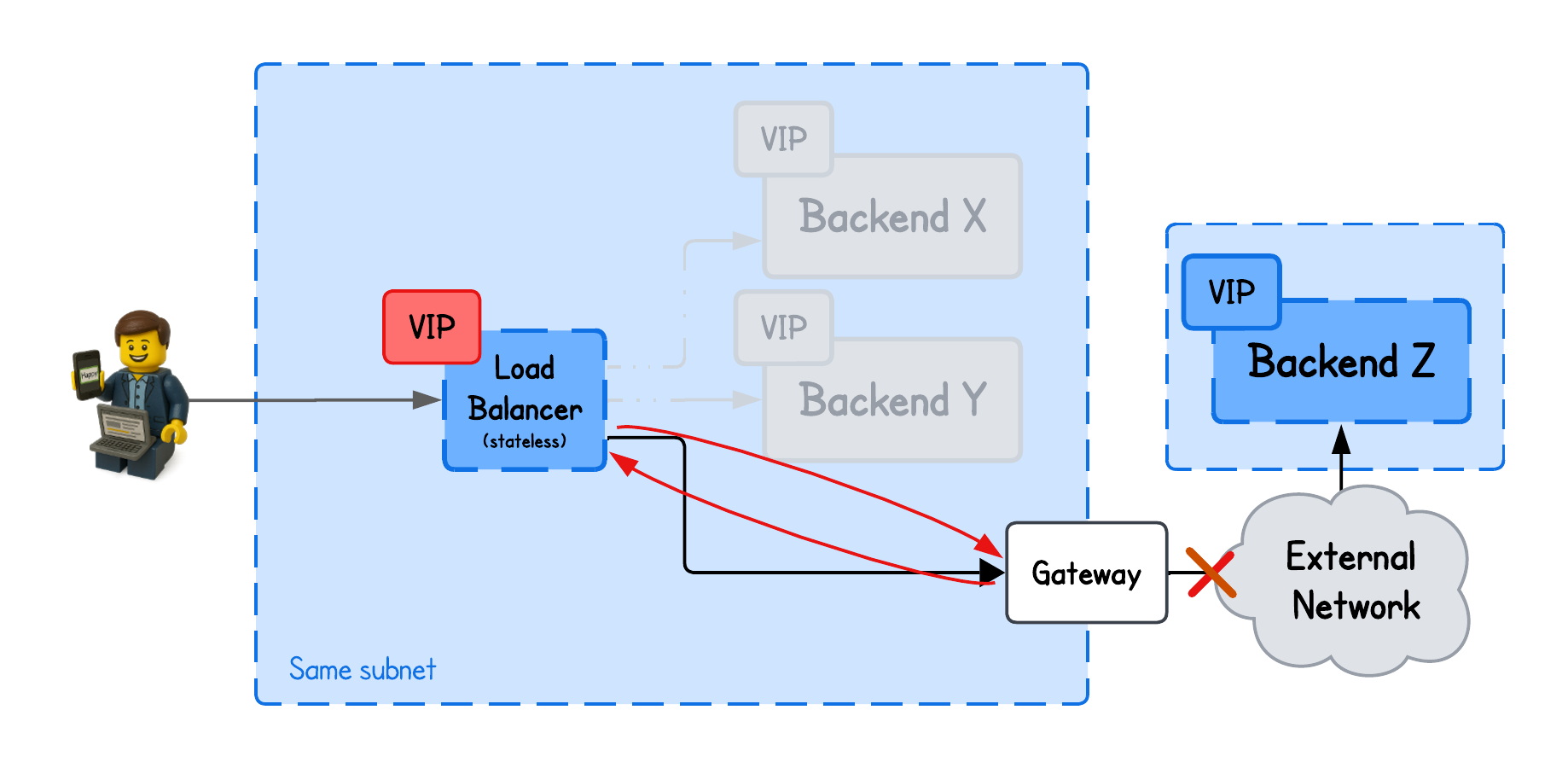
And this is quite a constraint for many setups to require the backends to share the same network as the load balancer.
Not to mention, hosting the load balancer and backend nodes on the same subnetwork also increases the risk of complete failures - network down → everything down.
This is where IPIP DSR Load balancing comes into play - but more about that in the upcoming tutorial.
About the Author
Writes about
Frequently covers